Table of Contents
Advertisement
Quick Links
Freescale Semiconductor, Inc.
User's Guide
TWR-KL43Z Tower Module
User's Guide
1
TWR-KL43Z
The TWR-KL43Z microcontroller module is designed to
work either in standalone mode or as part of the Freescale
Tower System, a modular development platform that enables
rapid prototyping and tool re-use through reconfigurable
hardware. Take your design to the next level and begin
constructing your Tower System today by visiting
Freescale.com/Tower for additional Tower System MCU
modules and compatible peripherals. For TWR-KL43Z
specific information and updates, visit
Freescale.com/TWR-KL43Z.
© 2014 Freescale Semiconductor, Inc. All rights reserved.
Document Number: TWRKL43ZUG
Rev. 1, 08/2014
Contents
1. TWR-KL43Z . . . . . . . . . . . . . . . . . . . . . . . . . . . . . . . 1
2. Contents . . . . . . . . . . . . . . . . . . . . . . . . . . . . . . . . . . . 2
3. TWR-KL43Z features . . . . . . . . . . . . . . . . . . . . . . . . . 2
4. Get to know the TWR-KL43Z . . . . . . . . . . . . . . . . . . 3
5. Reference documents . . . . . . . . . . . . . . . . . . . . . . . . . 3
6. Hardware description . . . . . . . . . . . . . . . . . . . . . . . . . 4
6.1. Block diagram . . . . . . . . . . . . . . . . . . . . . . . . . . . . . . . 4
6.2. Microcontroller . . . . . . . . . . . . . . . . . . . . . . . . . . . . . . 4
6.3. Clocking . . . . . . . . . . . . . . . . . . . . . . . . . . . . . . . . . . . 5
6.4. System power . . . . . . . . . . . . . . . . . . . . . . . . . . . . . . . 5
6.5. Real-time clock (RTC) . . . . . . . . . . . . . . . . . . . . . . . . 6
6.6. Debug interface . . . . . . . . . . . . . . . . . . . . . . . . . . . . . . 6
6.7. UART . . . . . . . . . . . . . . . . . . . . . . . . . . . . . . . . . . . . . 7
6.8. Infrared port . . . . . . . . . . . . . . . . . . . . . . . . . . . . . . . . 7
6.9. Accelerometer . . . . . . . . . . . . . . . . . . . . . . . . . . . . . . . 7
6.11. Potentiometer, pushbuttons, LEDs . . . . . . . . . . . . . . . 9
6.12. SLCD TWRPI interface . . . . . . . . . . . . . . . . . . . . . . . 9
6.13. USB . . . . . . . . . . . . . . . . . . . . . . . . . . . . . . . . . . . . . . 10
7. TWR-KL43Z jumper options . . . . . . . . . . . . . . . . . . 10
8. Useful links . . . . . . . . . . . . . . . . . . . . . . . . . . . . . . . . 12
9. Revision history . . . . . . . . . . . . . . . . . . . . . . . . . . . . 12
Advertisement
Table of Contents

Related Manuals for NXP Semiconductors TWR-KL43Z


Summary of Contents for NXP Semiconductors TWR-KL43Z
-
Page 1: Table Of Contents
Contents 1. TWR-KL43Z ....... 1 2. Contents ........2 The TWR-KL43Z microcontroller module is designed to 3. -
Page 2: Contents
Contents Figure 1. Freescale Tower system overview Contents The TWR-KL43Z module includes: • TWR-KL43Z board assembly • Three-foot A to micro-B USB cable for debug interface and power • Three-foot A to micro-B USB cable for MKL43Z256VLH4 USB interface •... -
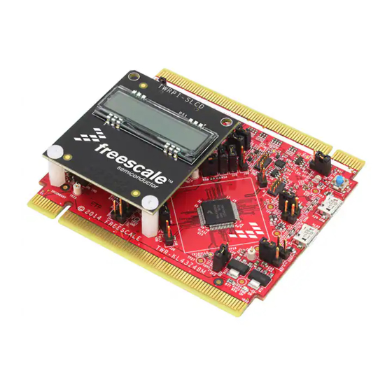
Page 3: Get To Know The Twr-Kl43Z
Figure 2. Front side of TWR-KL46Z48M module (TWRPI device not attached) Reference documents Reference the documents listed below for more information on the Kinetis family, Tower System, and MCU modules. These can be found in the documentation section at Freescale.com/TWR-KL43Z or Freescale.com/Kinetis. •... -
Page 4: Hardware Description
Hardware description Hardware description The TWR-KL43Z is a Tower MCU Module featuring the MKL43Z256VLH4 — a Kinetis microcontroller with USB 2.0 full-speed device controllers in a 64-LQFP package. It is intended for use in the Freescale Tower System but can operate standalone. An on-board OpenSDA debug circuit provides a SWD interface and a power supply input through a single USB mini-AB connector. -
Page 5: Clocking
(XTAL/EXTAL). A 32.768 KHz oscillator is connected to the real-time clock in input. System power When installed into a Tower System, the TWR-KL43Z can be powered from either an on-board source or from another source in the assembled Tower System. -
Page 6: Real-Time Clock (Rtc)
The Cortex Debug SWD connector is a standard 2x5-pin (0.05") connector providing an external debugger cable with access to the SWD interface of the MKL43Z256. Table 2. Cortex Debug connector Function TWR-KL43Z Connection VTref 3.3V MCU supply (V_BRD) SWDIO PTA3/I2C1_SCL/FTM0_CH0/SWD_DIO... -
Page 7: Uart
Hardware description UART UART2 can be connected to OpenSDA or TWR-Elevators through jumpers J3 and J5. J3 UART2_TX_TGTMCU – PTE22/UART2_TX J3 UART2_RX_TGTMCU – PTE23UART2_RX Figure 4. UART2 connection to OpenSDA CDC serial/elevator Infrared port An infrared transmit and receive interface is implemented as shown in Figure 5. -
Page 8: General Purpose Tower Plug-In (Twrpi) Socket
6.10 General Purpose Tower Plug-in (TWRPI) socket The TWR-KL43Z features a socket (J22 and J14) that can accept a variety of different Tower Plug-in modules featuring sensors, RF transceivers, and more. The General Purpose TWRPI socket provides access to I C, SPI, IRQs, GPIOs, timers, analog conversion signals, TWRPI ID signals, reset, and voltage supplies. -
Page 9: Potentiometer, Pushbuttons, Leds
Hardware description 6.11 Potentiometer, pushbuttons, LEDs The TWR-KL43Z features two pushbutton switches connected to GPIO/interrupt signals, one pushbutton connected to the master reset signal, four user-controllable LEDs, and a potentiometer connected to an ADC input signal. Refer to Table 5 for information about which port pins are connected to these features. -
Page 10: Usb
The MKL43Z256 features USB full-speed slave controller with on-chip transceiver and 5 V to 3.3 V regulator, supporting crystal-less recovery. The TWR-KL43Z routes the USB D+ and D- signals from the KL43Z256 MCU directly to the on-board USB connector (J21). - Page 11 TWR-KL43Z jumper options Table 6. Connectors and pin usage Default Jumper Function Jumper Jumper Option KL43 Pin Name Position Reset selection 1-2 RESET_B 2-3 RST_TGTMCU_B RTC clock input 1-2 RTC_CLKIN PTC1 2-3 ELEV_IRQ_C switch button SW2 Open - PTA4 isolated...
-
Page 12: Useful Links
Useful links Useful links • freescale.com/TWR-KL43Z • freescale.com • iar.com/freescale • pemicro.com • segger.com Revision history Table 7. Revision history Revision Date Description May, 2014 Initial release TWRKL43ZUG Tower Module, User’s Guide, Rev. 1, 08/2014 Freescale Semiconductor, Inc. - Page 13 How to Reach Us: Information in this document is provided solely to enable system and software implementers to use Freescale products. There are no express or implied copyright Home Page: licenses granted hereunder to design or fabricate any integrated circuits based on the freescale.com information in this document.
Need help?
Do you have a question about the TWR-KL43Z and is the answer not in the manual?
Questions and answers