Table of Contents
Advertisement
Quick Links
Freescale Semiconductor
Getting Started
TWR-LS1021A Getting Started
1
Introduction
This document describes how to connect the QorIQ
LS1021A Tower System Module (TWR-LS1021A-PB) board
and verify its basic operations such as the switches,
connectors, jumpers, push buttons and LED settings, and the
instructions for connecting the peripheral devices.
It is assumed that you are familiar with the LS1021A device
and the content of the TWR-LS1021A Reference Manual
(document TWR-LS1021ARM).
The prototype part number of the LS1021A tower board
system is X-TWR-LS1021A-PB and the production part
number is TWR-LS1021A-PB.
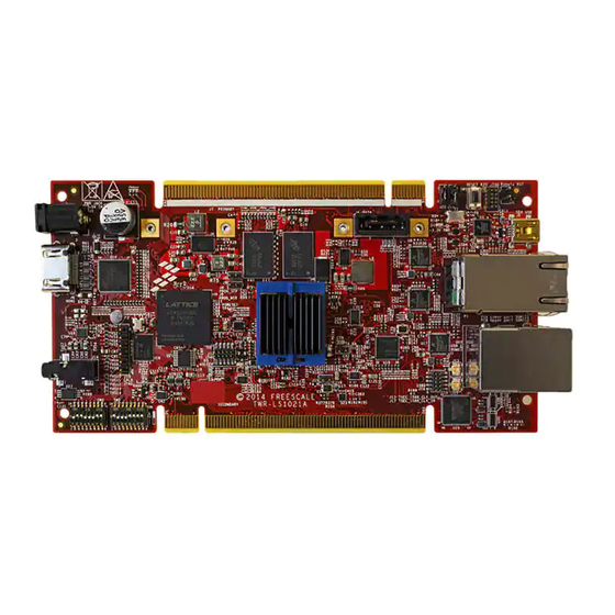
The figures listed below show the main features of the
secondary and primary sides of the TWR-LS1021A-PB
board.
© 2014-2015 Freescale Semiconductor, Inc. All rights reserved.
NOTE
Document Number: TWR-LS1021AGS
Contents
1. Introduction . . . . . . . . . . . . . . . . . . . . . . . . . . . . . . . . . 1
1.1.Related documentation . . . . . . . . . . . . . . . . . . . . . . 2
2. Switches and jumpers configuration . . . . . . . . . . . . . . 3
3. Connecting USB UART . . . . . . . . . . . . . . . . . . . . . . . 6
4. Initial board start-up . . . . . . . . . . . . . . . . . . . . . . . . . . 6
5. Board software configuration . . . . . . . . . . . . . . . . . . . 7
6. JTAG connectivity unit . . . . . . . . . . . . . . . . . . . . . . . . 8
6.1.Connecting JTAG using CodeWarrior TAP . . . . . . 9
6.2.Enabling CMSIS-DAP . . . . . . . . . . . . . . . . . . . . . . 9
7. TWR-LS1021A-PB OOBE demo . . . . . . . . . . . . . . . . 9
8. Revision History . . . . . . . . . . . . . . . . . . . . . . . . . . . . 10
Rev. 3, 10/2015
Advertisement
Table of Contents

Related Manuals for NXP Semiconductors TWR-LS1021A


Summary of Contents for NXP Semiconductors TWR-LS1021A
-
Page 1: Table Of Contents
NOTE 7. TWR-LS1021A-PB OOBE demo ....9 8. Revision History ......10... -
Page 2: Related Documentation
TWR-LS1021A-PB board. Some of the documents listed below may be available only under a non-disclosure agreement (NDA). To request access to these documents, contact your local field applications engineer or sales representative. TWR-LS1021A Getting Started, Rev. 3 Freescale Semiconductor... -
Page 3: Switches And Jumpers Configuration
Switches and jumpers configuration The TWR-LS1021A-PB board has two 8-way dual in line package (DIP) switch. The default DIP switch positions provide the working set up values for the board. You need to check the default positions and verify that the board is operational before changing the switches. - Page 4 » 0 : Vbank0 is selected (default) 1 : Vbank1 is selected S3.6 Signal multiplexed MUX_SEL selection 0 : 2D-ACE and LPUART1 are selected MUX_SEL » 1 : SPI2 and UCC1&3 are selected (default) TWR-LS1021A Getting Started, Rev. 3 Freescale Semiconductor...
- Page 5 Comments [OFF=0 ON=1] S3.7 Reserved Must be 0 [OFF] S3.8 Reserved Must be 1 [ON] The table below lists the jumper settings on the TWR-LS1021A-PB board. Table 3. Jumper settings Jumper Size Name/Function Description 1x2 pin PWR_PROG_SFP voltage setting Open: GND (default) Shorted: 1.8 V...
-
Page 6: Connecting Usb Uart
Then, select the first COM port assigned to the Virtual COM port. Initial board start-up The TWR-LS1021A-PB board is powered through a barrel connector. This barrel should be supplied by a 5 V @5 A supply. For more information, see... -
Page 7: Board Software Configuration
USB) Blink - Activity Board software configuration The NOR flash on the TWR-LS1021A-PB board is divided in two banks. There are different images in each banks that supports the different functionality. NOTE The TWR-LS1021A-PB board comes pre-programmed with the NOR flash image. -
Page 8: Jtag Connectivity Unit
Figure 6. TWR-LS1021A-PB block diagram JTAG connectivity unit This section explains the following two methods to configure the JTAG connectivity unit supported by the CodeWarrior Development Studio for QorIQ LS series on the TWR-LS1021A-PB board: • Section 6.1, “Connecting JTAG using CodeWarrior TAP”... -
Page 9: Connecting Jtag Using Codewarrior Tap
The out-of-box-experience (OOBE) is a demo program which shows the wireless networking, graphics and audio playing functionality of the TWR-LS1021A-PB. The image files for the demo are available in the SD card shipped with the board. You need to insert the SD card into the board to run the demo. -
Page 10: Revision History
Rev. 2 07/2015 Updated the TWR-LS1021A instances to TWR-LS1021A-PB. Figure 1 Primary side main features Updated the TWR-LS1021A board images with the TWR-LS1021A-PB board images. Figure 3 Default switch configuration Updated the figure for the default settings on SW3[1:8]. Table 2 Default switch settings Updated the table for the S2.6, S2.8, and S3.6 switch... - Page 11 Revision History TWR-LS1021A Getting Started, Rev. 3 Freescale Semiconductor...
- Page 12 How to Reach Us: Information in this document is provided solely to enable system and software implementers to use Freescale products. There are no express or implied copyright Home Page: freescale.com licenses granted hereunder to design or fabricate any integrated circuits based on the information in this document.
Need help?
Do you have a question about the TWR-LS1021A and is the answer not in the manual?
Questions and answers