
Subscribe to Our Youtube Channel
Related Manuals for NXP Semiconductors TWR-56F8400


Summary of Contents for NXP Semiconductors TWR-56F8400
- Page 1 TWR-56F8400 User Manual Rev. O.01 Freescale Semiconductor Inc. Microcontroller Solutions Group...
-
Page 2: Table Of Contents
Appendix A – Tower Elevator Connector Pin Functions .............. 20 Appendix B – TWR-56F8400 Board Schematic ................23 Appendix C – TWR-56F8400 Board BOM ..................24 Appendix D – TWR-56F8400 Board Jack Layout Top View ............1 TWR-56F8400 User’s Manual Page 2 of 35... - Page 3 Corrected TOWER signal names per latest. Included 0.03 6 March 2012 new functionality of S08 firmware for CDC serial port. Released to publications. 0.04 7 March 2012 JLW added back schematic as rev B TWR-56F8400 User’s Manual Page 3 of 35...
-
Page 4: Overview
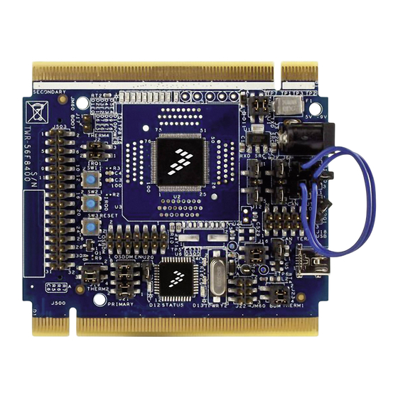
The MC56F8400 Tower 32-bit MCU Module (TWR-56F8400) is an evaluation, demonstration and development board. The TWR-56F8400 can operate stand-alone or as the main control board in a Tower system with peripheral modules. It can also be used as the main control board with an APMOTOR56F8000E motor control board. -
Page 5: Block Diagram
Voltage translators between 5V MC9S08JM60 MCU chip and 3.3V MC56F84789 DSC chip 1.1 Block Diagram A block diagram for the TWR-56F8400 is shown in Figure 1 below. Tower Elevator Expansion Connectors 5.0V 3.3V (SPI, I2C, ADC, FEC, TPM, SCI, KB, etc.) Barrel Power Connector Motor Control&... -
Page 6: Tower Mcu Module
2 Hardware Features This section provides more details about the features and functionality of the TWR-56F8400. A drawing of the TWR-56F8400 showing the jack locations is shown in Appendix D. Features are discussed below. 2.1 Tower MCU Module The TWR-56F8400 board is an MCU Module designed for standalone use (or with a Freescale Tower system) and complies with the electrical and mechanical specification as described in Freescale Tower Electromechanical Specification. -
Page 7: P3_3V/5V
The primary circuits on the board are related to the MC56F84789 DSC. This part is supplied in a surface mounted 100pin LQFP package at U2. Although the board was laid out to allow a ZIF socket at U3 in parallel to the chip at U2 the TWR-56F8400 is only available for purchase with the surface mounted chip. -
Page 8: Serial I/O Source Select Headers
2.3.2 Serial I/O Source Select Headers The TWR-56F8400 board allows the UART functions of the MC56F84789 DSC to be connected to a serial interface at the primary Tower Connector J500A or through a USB bridge to the Host PC using the OSBDM/OSJTAG MCU (U6). -
Page 9: Leds Controlled By The Mc56F84789 Dsc
LED. Table 3. LEDs Controlled by the MC56F84789 DSC LEDs Controlled by the MC56F84789 DSC MC56F84789 DSC MC56F84789 Pin Name Pin Number Reference Label Color GPIOE0/PWMA_0B Green GPIOE1/PWMA_0A Yellow GPIOE2/PWMA_1B Green GPIOE3/PWMA_1A Yellow TWR-56F8400 User’s Manual Page 9 of 35... -
Page 10: Motor Control Connector
3X/XB_IN2 2.3.4 Motor Control Connector The TWR-56F8400 board may be connected to a motor control board such as the APMOTOR56F8000E. The motor control connector (J501) is on the bottom of the board to provide a convenient connection to the motor control board. -
Page 11: Auxiliary Connectors
(With 100 ohms in series) 2.3.5 Auxiliary Connectors In addition to the motor control connector the TWR-56F8400 board also provides two auxiliary connectors (J502 and J503) on the bottom of the board. These connectors provide access to the MC56F84789 DSC signals that are not covered by the motor control connector. Those pins associated with analog inputs have 100 ohm resistors in series to provide some ESD protection for the analog inputs of the DSC. - Page 12 MC56F84789 DSC Signal GPIOF2/SCL1/XB_OUT6 GPIOF5/RXD1/XB_OUT9 GPIOC0/EXTAL/CLKIN0 GPIOF6/TB2/PWMA_3X/PWMB_3X/XB_I GPIOC1/XTAL GPIOF7/TB3/CMPC_O/SS1_B/XB_IN3 GPIOC2/TXD0/TB0/XB_IN2/CLKO0 GPIOF8/RXD0/TB1/CMPD_O GPIOC5/DACO/XB_IN7 GPIOC11/CANTX/SCL1/TXD1 GPIOC7/SS0_B/TXD0 GPIOC12/CANRX/SDA1/RXD1 GPIOC8/MISO0/RXD0/XB_IN9 GPIOC9/SCK0/XB_IN4 No Connection GPIOC10/MOSI0/XB_IN5/MISO0 No Connection No Connection No Connection No Connection GPIOA8/ANC16&CMPD_IN1 GPIOF12/MISO1/PWMB_FAULT2 GPIOA9/ANC17&CMPD_IN2 GPIOF13/MOSI1/PWMB_FAULT1 GPIOA10/ANC18&CMPD_IN3 GPIOF14/SCK1/PWMB_FAULT0 TWR-56F8400 User’s Manual Page 12 of 35...
- Page 13 MC56F84789 DSC Signal GPIOA11/ANC19&VREFHC GPIOF15/RXD0/XB_IN10 GPIOB8/ANC20&VREFLC GPIOG0/PWMB_1B/XB_OUT6 GPIOB9/ANC21/XB_IN9/MISO2 GPIOG1/PWMB_1A/XB_OUT7 GPIOB10/ANC22/XB_IN8/MOSI2 GPIOG2/PWMB_0B/XB_OUT4 GPIOB11/ANC23/XB_IN7/SCK2 GPIOG3/PWMB_0A/XB_OUT5 GPIOD5/RXD2/XB_IN5/XB_OUT9 GPIOG4/PWMB_3B/PWMA_FAULT2 GPIOD6/TXD2/XB_IN4/XB_OUT8 GPIOG5/PWMB_3A/PWMA_FAULT3 GPIOD7/XB_OUT11/XB_IN7/MISO1 GPIOG6/PWMA_FAULT4/PWMB_FAULT4/TB2 /XB_OUT8 GPIOE8/PWMB_2B/PWMA_FAULT0 GPIOG7/PWMA_FAULT5/PWMB_FAULT5/XB_ OUT9 GPIOE9/PWMB_2A/PWMA_FAULT1 GPIOG8/PWMB_0X/PWMA_0X/TA2/XB_OUT1 GPIOF9/ GPIOG9/PWMB_1X/PWMA_1X/TA3/XB_OUT1 RXD2/PWMA_FAULT7/PWMB_FAULT7/X B_OUT11 GPIOF10/TXD2 GPIOG10/PWMB_2X/PWMA_2X/XB_IN8/SS_B /PWMA_FAULT6/PWMB_FAULT6/XB_OU GPIOF11/TXD0/XB_IN11 GPIOG11/TB3/CLKO0/MOSI1 TWR-56F8400 User’s Manual Page 13 of 35...
-
Page 14: Tower Elevator Connectors
2.3.8 CAN Transceiver The TWR-56F8400 board has a CAN transceiver circuit that may be connected to the CAN pins of the DSC. The CAN transceiver (U503) can be connected to the GPIOC11/CANTX/SCL1/TXD1 and GPIOC12/CANRX/SDA1/RXD1 pins of the DSC through the header at J16. Installing a shunt from pin 1 to pin 2 connects the TXD nets and installing a shunt from pin 3 to pin 4 connects the RXD nets. -
Page 15: Irq Or Input Pushbuttons
JTAG port, rather than the ‘JM60. The TWR-56F8400 board provides a 2.2K ohm pull up resistor to 3.3V on the TMS line. If an external JTAG aware debugger also has a pull up on this line, the external debugger may not be able to pull the TMS line low. -
Page 16: Osbdm/Osjtag
2.4.4 Reserved Function Select Header Header J20 selects whether the on-board MC9S08JM60 MCU operates as an OSBDM/OSJTAG debug interface or as a USB Serial Bridge interface on older versions of S08 firmware such as may have existed TWR-56F8400 User’s Manual Page 16 of 35... -
Page 17: Bootloader Enable
(no power to the USB connector). In that case the OUT_EN signal from the OSBDM/OSJTAG MCU (pin 15) is biased low by R12. The inverter at U502B then drives OUT_EN_B high in response. Additional information is included in section 2.4.2. TWR-56F8400 User’s Manual Page 17 of 35... -
Page 18: Jumper Table
3 Jumper Table There are several headers provided for isolation, configuration, and feature selection. Refer to Table 6 for details. The default shunt positions are shown in bold. Table 6. TWR-56F8400 Jumper Table Jumper Function Shunts Description 1-2, 3-4 Connect RT1 circuit to the MC56F827 DSC... - Page 19 (JTAG) to the MC56F84789 DSC JTAG pins JTAG Disconnect OSBDM/OSJTAG from the MC56F84789 none 1-2, 3-4 Connect RT4 circuit to the MC56F827 DSC Thermistor RT4 Connect none Disconnect RT4 circuit from the MC56F84789 DSC TWR-56F8400 User’s Manual Page 19 of 35...
-
Page 20: Appendix A - Tower Elevator Connector Pin Functions
Note that all analog pins (ANAn or ANBn) have a low pass filter to ground consisting of a 100 ohm resistor and a 2200 pf capacitor. This is to protect the analog inputs of the DSC from a static discharge at one of the connectors. See schematic sheets 6 and 7 in Appendix B – TWR-56F8400 Board Schematic. - Page 21 TWR-56F8400 Primary Connector Name Usage Used Jmp Pin Name Usage Used Jmp I2S0_DOUT_WS GPIO3 GPIOB6/ANB6&CMPB_M1 I2S0_DOUT_DIN0 CLKIN0 XTAL&CLKIN I2S0_DOUT_DOUT0 CLKOUT1 GND_4 Ground GND_12 Ground ANB3&CMPC_M0 ANA3&CMPA_M2 ANB2&CMPC_P2 ANA2&CMPA_M1 ANB1&VERFLB&CMPB_M0 ANA1&VREFLA&CMPA_M0 ANB0&VERFHB&CMPB_P2 ANA0&VREFHA&CMPA_P2/CMPC_O GND_5 Ground GND_13 Ground DAC1 DAC0 DAC0 TMR3...
- Page 22 TWR-56F8400 Primary Connector Name Usage Used Jmp Pin Name Usage Used Jmp EBI_AD16 EBI_AD13 EBI_AD17 EBI_AD12 EBI_AD18 EBI_AD11 EBI_AD19 EBI_AD10 EBI_R/ W_b EBI_AD9 EBI_OE_b EBI_AD8 EBI_D7 EBI_AD7 EBI_D6 EBI_AD6 EBI_D5 EBI_AD5 EBI_D4 EBI_AD4 EBI_D3 EBI_AD3 EBI_D2 EBI_AD2 EBI_D1 EBI_AD1 EBI_D0...
-
Page 23: Appendix B - Twr-56F8400 Board Schematic
Appendix B – TWR-56F8400 Board Schematic The Schematic supplied a standalone PDF file. Please go to www.freescale.com/TWR-56F8400 download. TWR-56F8400 User’s Manual Page 23 of 35... -
Page 24: Appendix C - Twr-56F8400 Board Bom
Appendix C – TWR-56F8400 Board BOM The BOM is supplied as an embedded worksheet object, just below. Right click on the object below and select “Worksheet Object”, then “Open” to read the BOM or work with it as a spreadsheet. - Page 25 TEST POINT PIN .100 x .45 BLACK TH J4,J5,J7,J11 Pinrex 210-91-03GB01 HDR 1X3 TH 100MIL SP 339H AU 118L Enterprise Co., 77311-801-03LF HDR 1X3 TH 100MIL SP 339H AU 118L SAMTEC TSW-103-07-S-S HDR 1X3 TH 100MIL SP 339H AU 118L TWR-56F8400 User’s Manual Page 25 of 35...
- Page 26 HDR 2X4 SMT 100MIL CTR 409H AU CORPORATIO N LIMITED 98401-101A08LF HDR 2X4 SMT 100MIL CTR 393H AU ANYTRONIC 090092H05015N6T-2LF HDR 2X5 SMT 100MIL CTR 414H AU CORPORATIO N LIMITED 98401-801A10LF HDR 2X5 SMT 100MIL CTR 400H AU TWR-56F8400 User’s Manual Page 26 of 35...
- Page 27 IC BUF QUAD TS 1.65-3.6V TSSOP14 SEMICONDUC TORS TEXAS SN74LVC125APWG4 IC BUF QUAD TS 1.65-3.6V TSSOP14 INSTRUMENTS U504 TEXAS SN74HCT125D IC BUF QUAD TS 4.5-5.5V SOIC14 INSTRUMENTS U503 PHILIPS PCA82C250T/N4 IC XCVR CAN 1MBAUD 5V S08 SEMICONDUC TWR-56F8400 User’s Manual Page 27 of 35...
- Page 28 RES MF 100 OHM 1/16W 1% 0402 512,R513,R51 INTERTECHNO 4,R515,R516, LOGY R517,R518,R 519,R520,R52 1,R522,R523, R524,R525,R 526,R529,R53 0,R531,R532, R533,R534,R 535,R537,R53 8,R540,R541, R542,R543,R 544,R545,R54 6,R547,R548, R549,R550,R 551,R552,R55 VENKEL CR0402-16W-1000FT RES MF 100 OHM 1/16W 1% 0402 COMPANY TWR-56F8400 User’s Manual Page 28 of 35...
- Page 29 RES MF ZERO OHM 1/8W -- 0805 VENKEL CR0805-8W-000T RES MF ZERO OHM 1/8W -- 0805 COMPANY VISHAY CRCW0805000RJNEA RES MF ZERO OHM 1/8W -- 0805 INTERTECHNO LOGY KOA SPEER RK73Z2ATTD RES MF ZERO OHM 1/8W -- 0805 TWR-56F8400 User’s Manual Page 29 of 35...
- Page 30 RES MF 330 OHM 1/16W 1% 0402 TECHNOLOGY CORP. THYE MING CR-02FL6--330R RES MF 330ohm 1/16W 1% 0402 TECH CO LTD THYE MING CR02FL6--10M RES MF 10M 1/16w 1% 0402 TECH CO LTD TWR-56F8400 User’s Manual Page 30 of 35...
- Page 31 SKT 100 LQFP TH 0.5MM 846H -- 89L ELECTRONICS FREESCALE PC56F84789VLL IC CTLER DSP 32BIT LQFP100 SEMICONDUC C5,C6 KEMET C0805C220J5GAC CAP CER 22PF 50V 5% C0G CC0805 08055A220JAT2A CAP CER 22PF 50V 5% C0G 0805 TWR-56F8400 User’s Manual Page 31 of 35...
- Page 32 XTAL 8MHZ SER SMT INTERNATION FREESCALE PC56F84789VLL IC CTLER DSP 32BIT LQFP100 SEMICONDUC R536 VISHAY CRCW0402100RFKED RES MF 100 OHM 1/16W 1% 0402 INTERTECHNO LOGY VENKEL CR0402-16W-1000FT RES MF 100 OHM 1/16W 1% 0402 COMPANY TWR-56F8400 User’s Manual Page 32 of 35...
- Page 33 RES MF 1.0K 1/16W 1% 0402 VISHAY CRCW-0402-1K00-FK-E3 RES MF 1.0K 1/16W 1% 0402 INTERTECHNO LOGY KOA SPEER RK73H1ETTP1001F RES MF 1.0K 1/16W 1% 0402 THYE MING CR-02FL6----1K RES MF 1.0K 1/16W 1% 0402 TECH CO LTD TWR-56F8400 User’s Manual Page 33 of 35...
- Page 34 RES MF 1.0K 1/16W 1% 0402 KOA SPEER RK73H1ETTPL1001F RES MF 1.0K 1/16W 1% 0402 Rohm MCR01MZPF1001 RES MF 1.0K 1/16W 1% 0402 Semiconductor KNOWLES SPM0408HE5H-SB MICROPHONE MINI SISONIC 300 OHM ACOUSTICS 59DB 1.5-3.6V SMT TWR-56F8400 User’s Manual Page 34 of 35...
-
Page 35: Appendix D - Twr-56F8400 Board Jack Layout Top View
Appendix D – TWR-56F8400 Board Jack Layout Top View T WR 56F8400 T O P A ll num bers Jack or P in designation FUSE 17-1 503-1 11-3 13-2 13-1 13-9 14-2 16-1 15-2 14-1 15-1 21-8 20-1 16-4 19-1...
Need help?
Do you have a question about the TWR-56F8400 and is the answer not in the manual?
Questions and answers