Table of Contents
Advertisement
Quick Links
Assembly Instructions
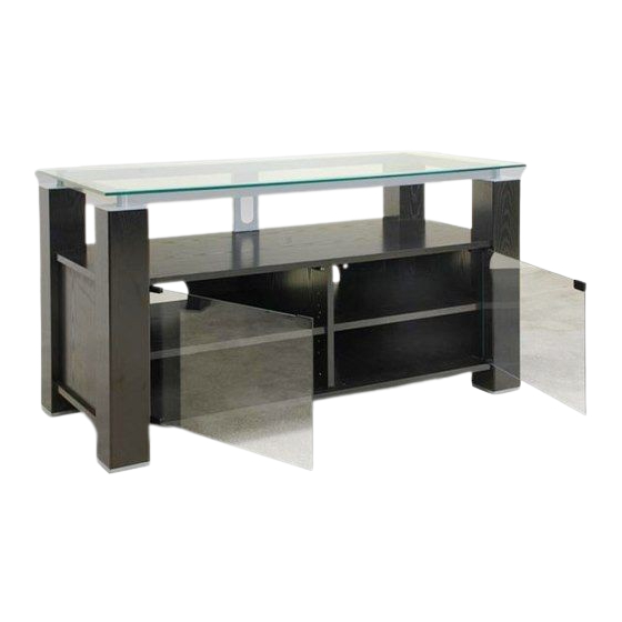
47" WIDE TV STAND, AUDIO/VIDEO COMBINATION UNIT
OVERALL DIMENSIONS: 26" H x 47" W x 21
EL-905:
(A rich, deep brown-black, wood-grain finish)
EL-955:
PARTS
1. Glass Top
2. Fixed Top & Bottom
Wooden Panels (2 identical)
3. Leg A (2 identical,
Front Left, Rear Right)
4. Leg B (2 identical,
Front Right, Rear Left)
5. Center Vertical Support Panel
Hardware for unit assembly
A
20
B
Connecting
Bolts
D
1
E
Hex Key
1-3/16" Bolts for
Tool
G
8
H
Self-Adhesive
5/8" Screws for
Spacer Disk for
under Glass Top
K
4
L
CHROME
5/8" Screws for
Plastic Camlock
Magnetic Latch
P
4
Q
Plastic
Bushings
FOR PARTS & CUSTOMER SERVICE PLEASE CALL 1-800-ELITE-48
CUSTOMER SERVICE HOURS EASTERN TIME 8:45 AM - 4:45 PM M-F
Thank you for purchasing this Elite product. You will need the following tools:
• Phillips Head Screw Driver • Straight Blade Screw Driver • Rubber Padded Hammer or Mallet
Wenge Melamine
Gray Melamine
6. Side Panels (2 identical)
7. Adjustable Shelf (2 identical)
8. Long Metal Rails (2 identical)
9. Short Metal Rails (2 identical)
10. Back Panel
11. Wire Management
Channel
12. Glass Door (2 identical)
C
20
Wooden
Camlocks
Dowels
F
4
Plastic Glass
Cushion
Metal Rails
12
J
CHROME
BLACK
11/16" Screws
for Wire
Back Panel
Management
M
16
2
8
Covers
Glass Door Hinges
4
R
Metal Strike
Protective
Plates
Plates
PLEASE DO NOT RETURN UNIT TO STORE
/
3
"D
4
20
4
4
6
3
2
12
N
2
2
Magnetic Touch
Latch
2
S
2
Foam Protective
Pads
/
21
3
"
4
47"
1
9
8
8
9
2
7
7
5
2
4
12
T
8
U
1" Long Metal
Plastic Hole
Shelf Pins
26"
11
10
3
6
4
Covers
Advertisement
Table of Contents

Related Manuals for Elite Industries EL-905


Summary of Contents for Elite Industries EL-905
- Page 1 • Phillips Head Screw Driver • Straight Blade Screw Driver • Rubber Padded Hammer or Mallet Assembly Instructions " 47" 47" WIDE TV STAND, AUDIO/VIDEO COMBINATION UNIT OVERALL DIMENSIONS: 26" H x 47" W x 21 "D EL-905: Wenge Melamine (A rich, deep brown-black, wood-grain finish) EL-955: Gray Melamine 26" PARTS 6.
- Page 2 IMPORTANT NOTES & CAUTIONS/WARNINGS • Carefully read and follow these instructions for assembly. • Please handle parts carefully, some parts may be heavy and can have sharp edges – we recommend possibly using cloth protective gloves for extra protection. • To protect the unit and your flooring surface we recommend working on a padded or carpeted area, you may also use the open box the unit came in for this purpose.
- Page 3 PREPARATION OF LEFT & RIGHT SIDE PANELS & CENTER VERTICAL SUPPORT PANEL Insert Wooden Dowels (C) and Camlocks (B) into Center Vertical Support Panel as shown. Note that front edge of Center Divider Panel is finished. Insert Wooden Dowels (C) and Camlocks (B) into Some holes on this panel are not used in each Side Panel (6) as shown.
- Page 4 ATTACH LEGS CAMLOCK/CONNECTING BOLT PROCEDURE MAKE SURE AS YOU ATTACH LEGS THAT TOP IS UP. ALL HOLES TO ATTACH METAL RAILS IN STEP 6 ARE AT TOP OF LEG. JOIN PIECES TOGETHER TURN CAMLOCKS ALIGN CAMLOCK 180° CLOCKWISE USING WITH A FLATHEAD CONNECTING BOLT SCREWDRIVER...
- Page 5 ATTACH BACK PANEL ATTACH WIRE MANAGEMENT CHANNEL Attach 2 Self-adhesive ATTACH 2 Spacer Disks (G) to Wire SELF- ADHESIVE Management Channel (11) DISKS TO between Wire Management FRONT OF Channel (11) and Long WIRE Metal Rail as shown. MANAGEMENT CHANNEL Using 2 Screws (J) attach Wire Management...
- Page 6 ADD SHELF PINS AND POSITION ADJUSTABLE SHELVES Insert 4 Metal Shelf Pins (T) at desired height for each Adjustable Shelf (7). Carefully slide each Adjustable Shelf (7) into unit from the front and rest it on Shelf Pins (T). ADD BUSHINGS FOR GLASS DOORS Insert 4 Plastic Bushings (P) to Top and Bottom Wooden...
- Page 7 ADD GLASS DOORS Fit top hinge (M) over top corner of glass door. STEP 1 Slip protective plate (Q) between glass and hinge setting screws. Slightly tighten screws carefully. Insert bottom hinge (M) into bottom Plastic Bushing (P) and slip door into hinge, after inserting top corner.
- Page 8 Distributed by: Elite Industries, 77 Gould Street • Bayonne, NJ 07002, Tel.: 201-436-1120 • Fax: 201-436-6960 Elite Industries ensures complete satisfaction with this product. In the event of missing or damaged parts...
Need help?
Do you have a question about the EL-905 and is the answer not in the manual?
Questions and answers