Advertisement
Table of Contents
- 1 Models and Specifications
- 2 Technical Parameters
- 3 Wiring Diagram
- 4 Safety Warning
- 5 Panel Instruction
- 6 Connecting Sensors
- 7 Workflow for Setting
- 8 Defining Parameter for Alarm ALP
- 9 Adjustment Mode Parameter "Ctrl
- 10 Field Parameter "EP1 - EP8
- 11 Solenoid Valve or Relay Control
- Download this manual
http://waterheatertimer.org/Add-another-thermostat-to-gas-or-electric-water-heater.html
Safety warning ...................................................................................................................................................2
Product features .................................................................................................................................................2
1.Technical parameters ........................................................................................................................................2
2.Models and specifications ...................................................................................................................................2
3.Diagram and installing size .................................................................................................................................2
4.Wiring diagram ................................................................................................................................................2
4.1 Connecting sensors ......................................................................................................................................3
4.1.1 Thermocouple ..........................................................................................................................................3
4.1.2 Dual lines PT100 sensor..............................................................................................................................3
4.1.3 RTD sensor..............................................................................................................................................3
4.2 Power supply connection ................................................................................................................................3
4.3 connection for control signal output ..................................................................................................................3
4.4 Connection for alarm control ...........................................................................................................................3
5.Panel instruction ...............................................................................................................................................3
6.Operation instruction ..........................................................................................................................................3
6.1Display status ...............................................................................................................................................3
6.2 View output value ..........................................................................................................................................3
6.3 Automatic/Manual control switch .....................................................................................................................3
6.4 Value setting ................................................................................................................................................3
6.5 Launch self-tuning function ..............................................................................................................................3
6.6 Workflow for setting .......................................................................................................................................4
6.7 Parameters setting .......................................................................................................................................4
6.8 Parameters related to alarm output: "HiAL,LoAL,dHAL,dHAL,dF,ALP,CF" ....................................................................5
6.8.1 Alarm parameters: HiAL,LoAL,dHAL,dHAL .....................................................................................................5
6.8.2 Defining parameter for alarm ALP ..............................................................................................................5
6.8.3 Hysteresis Band dF .................................................................................................................................5
6.8.4 Function parameter CF .............................................................................................................................5
6.9 Parameters related to input "Sn,diP,diL,diH,DL,Sc" ..............................................................................................5
6.9.1 Sensor type input "Sn" ..............................................................................................................................5
6.9.2 Decimal point position"diP" ........................................................................................................................5
6.9.3 Definition parameters "diH" and "diL" for linear input range ................................................................................5
6.9.4 Filtering parameter"dL"..............................................................................................................................5
6.9.5 Sensor Calibration"Sc"..............................................................................................................................5
6.10 Parameters related to control output"oPI,oPL,oPH,CtrL" .......................................................................................5
6.10.1 Output mode parameters "oPI", "oPL" and "oPH" are used for limiting output ........................................................5
6.10.2 Adjustment mode parameter "CtrL" ............................................................................................................6
6.11 PID control parameters related to self-tuning "M50, P, t" and functional parameter "CtL"............................................6
6.11.1 6.11.1 Holding parameter "M50" .................................................................................................................6
6.11.2 Rate parameter "P" ...............................................................................................................................6
6.11.3 Hysteresis time "t"...................................................................................................................................6
6.11.4 Function parameter "CtL" .........................................................................................................................6
6.12 Communication parameter "Addr、bAud" .........................................................................................................6
6.13 Field parameter "EP1 - EP8" ..........................................................................................................................7
6.14 Permission for parameters "Loc""LOC" .........................................................................................................7
6.15 Common faults and handling methods .............................................................................................................7
7 Wiring instruction .............................................................................................................................................7
7.1 Directly control load by the internal relay of the instrument ......................................................................................7
7.2 Control the load via external contactor ...............................................................................................................7
7.3 SSR control ..............................................................................................................................................7
7.4 Solenoid valve or relay control .......................................................................................................................8
7.5 Control load via external contactor (24V) ...........................................................................................................8
8.Field application example ...................................................................................................................................8
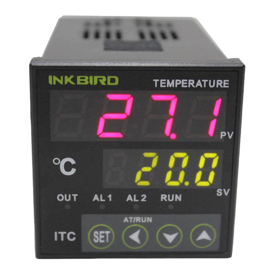
ITC-100 PID Temperature Controller
User Manual
Contents
© 2015 Inkbird Inc. All rights reserved.
1
V1.0 2015-6-30
www.ink-bird.com, CS@ink-bird.com
Advertisement
Table of Contents

Related Manuals for Inkbird ITC-100


Summary of Contents for Inkbird ITC-100
- Page 1 7.2 Control the load via external contactor …………………………………………………………………………………………...……7 7.3 SSR control ……………………………….……………………………………………………………………………………………7 7.4 Solenoid valve or relay control ………..………………………………………………………………………………………………8 7.5 Control load via external contactor (24V) …………………………………………………………………………………………..…8 8.Field application example …………………………………………………………………………………………………………………..8 © 2015 Inkbird Inc. All rights reserved. www.ink-bird.com, CS@ink-bird.com...
-
Page 2: Models And Specifications
About 140g Working temperature -10 - 55º C (No ice or moisture condensation) Working humidity RH 35-85% Figure 4:Wiring diagram Storing temperature -25 - 65º C (No ice or moisture condensation) © 2015 Inkbird Inc. All rights reserved. www.ink-bird.com, CS@ink-bird.com... -
Page 3: Panel Instruction
1 second to switch automatic and manual mode. “SET” key when in normal display mode, press this key to view setting value for control signal output; long press for over 2 seconds to enter parameters setting mode. © 2015 Inkbird Inc. All rights reserved. www.ink-bird.com, CS@ink-bird.com... -
Page 4: Workflow For Setting
Ctl:Control period run:Running status LOC:Permission of Sn:Input sensor revising parameter diP:decimal place EP1-EP8:8 definitions for field parameter diL:Displayed value for low limit Figure 6:Workflow for setting © 2015 Inkbird Inc. All rights reserved. www.ink-bird.com, CS@ink-bird.com... -
Page 5: Defining Parameter For Alarm Alp
When B=0, LoAL alarm is output by AL1; When B=2, LoAL alarm is output by AL2; ITC-100 has in-built digital filtering system. When the displayed value is When C=0, dHAL alarm is output by AL1; not stable due to input interference, use digital filtering to smooth it. -
Page 6: Adjustment Mode Parameter "Ctrl
63.5% of its maximum heating rate when heating with a fixed power. 6.10.2 Adjustment mode parameter "CtrL" ITC-100 allows digital adjustment or professional PID adjustment. 6.11.4 Function parameter "CtL" Select it by CtrL parameter. -
Page 7: Field Parameter "Ep1 - Ep8
SSR is a kind of electronic switch without contactor, which can be output used for higher frequency control than relay, featuring more stable temperature control for heater and long lifetime. © 2015 Inkbird Inc. All rights reserved. www.ink-bird.com, CS@ink-bird.com... -
Page 8: Solenoid Valve Or Relay Control
For simple users, no need to master all instructions, as long as the parameters of the following parameters in the process to set up to get the ideal control effect, set up flow chart as below: © 2015 Inkbird Inc. All rights reserved. www.ink-bird.com, CS@ink-bird.com... - Page 9 Setting System Keep the Default value. functions selection 2:Heater, 3:Cooler Setting Permission of Keep the Default value revising parameter 8 definitions for field Keep the Default value parameter Figure 15:Workflow of sample © 2015 Inkbird Inc. All rights reserved. www.ink-bird.com, CS@ink-bird.com...
Need help?
Do you have a question about the ITC-100 and is the answer not in the manual?
Questions and answers