Table of Contents
Advertisement
Quick Links
Download this manual
See also:
User Manual
Advertisement
Table of Contents

Related Manuals for YOKOGAWA AQ7280 OTDR


Summary of Contents for YOKOGAWA AQ7280 OTDR
- Page 1 User’s AQ7280 OTDR Manual Getting Started Guide IM AQ7280-02EN 6th Edition...
-
Page 2: List Of Manuals
• Every effort has been made in the preparation of this manual to ensure the accuracy of its contents. However, should you have any questions or find any errors, please contact your nearest YOKOGAWA dealer. • Copying or reproducing all or any part of the content of this manual without the permission of YOKOGAWA is strictly prohibited. 6th Edition: December 2017 (YMI) All Rights Reserved, Copyright ©... - Page 3 Trademarks • Microsoft, Windows, Windows 7, and Windows 8 are either registered trademarks or trademarks of Microsoft Corporation in the United States and/or other countries. • Adobe and Acrobat are trademarks of Adobe Systems Incorporated. • In this manual, the ® and TM symbols do not accompany their respective registered trademark or trademark names. •...
-
Page 4: Product Registration
Product Registration Thank you for purchasing YOKOGAWA products. YOKOGAWA provides registered users with a variety of information and services. Please allow us to serve you best by completing the product registration form accessible from our website. http://tmi.yokogawa.com/ IM AQ7280-02EN... -
Page 5: Checking The Package Contents
After receiving the product and opening the package, check the items described below. If the wrong items have been delivered, if items are missing, or if there is a problem with the appearance of the items, contact your nearest YOKOGAWA dealer. - Page 6 OTDR unit xxx-xxxx Model Suffix Description AQ7282A 2WL 1310/1550 nm 38/36 dB AQ7283A 2WL 1310/1550 nm 42/40 dB AQ7284A 2WL 1310/1550 nm 46/45 dB AQ7285A 2WL 1310/1550 nm 50/50 dB AQ7283E 3WL 1310/1550,1625 nm 42/40, 40 dB (1625 nm port is equipped with a built-in filter) AQ7283F 3WL 1310/1550,1650 nm 42/40, 40 dB (1650 nm port is equipped with a built-in filter) AQ7282G...
- Page 7 Optical power meter module (OPM module) xxx-xxxx Model Suffix Description AQ2780 OPM module Power range: –70 dBm to +10 dBm (CW) AQ2781 High power OPM module Power range: –50 dBm to +27 dBm (CW) AQ2780V OPM & VLS module Power range: –70 dBm to +10 dBm (CW) with Visible Light Source (Connector: Ø2.5 Ferrule) AQ2781V High power OPM &...
- Page 8 AQ4780 Visible light source module xxx-xxxx Model Suffix Description AQ4780 VLS module Visible Light Source (Connector: Ø2.5 Ferrule) For products whose suffix code contains “Z,” an exclusive manual may be included. Please read it along with the standard manual. No. (Instrument number) When contacting the dealer from which you purchased the instrument, please tell them the instrument number.
- Page 9 2 If a VLS or optical power meter module has not been ordered along with the OTDR mainframe (AQ7280), the cover is attached to the OTDR mainframe. 3 You can purchase the printed IM AQ7280-01EN and IM AQ7280-17EN manuals separately. Contact your nearest YOKOGAWA dealer to purchase a copy.
- Page 10 CD. File Name Manual Title Manual No. Features and Operation Manual.pdf AQ7280 OTDR User’s Manual IM AQ7280-01EN Communication Interface.pdf AQ7280 OTDR Communication Interface User’s Manual IM AQ7280-17EN To view above manuals you need Adobe Reader 5.0 or later. IM AQ7280-02EN...
-
Page 11: Safety Precautions
This manual is an essential part of the product; keep it in a safe place for future reference. YOKOGAWA assumes no liability for the customer’s failure to comply with these requirements. - Page 12 Failure to comply with the precautions below could lead to injury or death. WARNING Use the Instrument Only for Its Intended Purpose This optical measuring instrument is designed to measure the optical characteristics of light sources and evaluate their performance. Do not use this instrument for anything other than as an optical measuring instrument. Check the Physical Appearance Do not use the instrument if there is a problem with its physical appearance.
- Page 13 Do not use the instruments in the presence of flammable gasses or vapors. Doing so is extremely dangerous. Do Not Remove the Covers or Disassemble or Alter the Instrument Only qualified YOKOGAWA personnel may remove the covers and disassemble or alter the instrument. Installation Position Handling the stand without firmly supporting the instrument can be dangerous.
- Page 14 French AVERTISSEMENT Utiliser l’instrument aux seules fins prévues Cet instrument de mesure optique est prévu pour mesurer les caractéristiques optiques des sources lumineuses et évaluer leur performance. Ne pas utiliser cet instrument à d’autres fins que celles de mesure optique. Inspecter l’apparence physique Ne pas utiliser l’instrument si son intégrité...
- Page 15 Ne pas retirer le capot, ni démonter ou modifier l’instrument Seul le personnel YOKOGAWA qualifié est habilité à retirer le capot et à démonter ou modifier l’instrument. Certains composants à l’intérieur de l’instrument sont à haute tension et par conséquent, représentent un danger.
- Page 16 Safety Precautions for Laser Products This instrument uses a laser light source. This instrument is a Class 1M and Class 3R laser product as defined by IEC/EN60825-1:2007 Safety of Laser Products—Part1: Equipment classification and requirements. In addition, this instrument complies with 21 CFR 1040.10 except for deviations pursuant to Laser Notice No.
- Page 17 OTDR unit (AQ7284A, AQ7285A, AQ7284H, AQ7283J, AQ7283K) Laser Class 1M Label Using an optical instrument, such as a loupe, magnifying glass, or microscope, when observing the laser beam from a distance of less than 100 mm may cause eye injury. Laser Class 3R Label Avoid direct eye exposure.
- Page 18 OTDR unit (AQ7282A, AQ7283A, AQ7283E, AQ7283F, AQ7282G, AQ7283H) Laser Class 1M Label Using an optical instrument, such as a loupe, magnifying glass, or microscope, when observing the laser beam from a distance of less than 100 mm may cause eye injury. IM AQ7280-02EN...
- Page 19 OTDR unit (AQ7282M) Laser Class 1M Label Using an optical instrument, such as a loupe, magnifying glass, or microscope, when observing the laser beam from a distance of less than 100 mm may cause eye injury. Laser Class 3R Label Avoid direct eye exposure.
- Page 20 OPM module (AQ2780V, AQ2781V) Laser Class 3R Label Avoid direct eye exposure. VLS module (AQ4780) Laser Class 3R Label Avoid direct eye exposure. IM AQ7280-02EN...
- Page 21 OTDR unit Model Class Center Maximum Output Power Mode Field Beam Wavelength Diameter Divergence AQ7282A 1M 1310 nm/1550 nm CW: 50 mW@1310 nm/1550 nm 9 μm 11.5° PULSE: 200 mW@1310 nm/1550 nm PULSE width: 20 μs@1310 nm/1550 nm, Duty: ≤ 3.0% AQ7283A 1M 1310 nm/1550 nm CW: 50 mW@1310 nm/1550 nm...
- Page 22 Model Class Center Maximum Output Power Mode Field Beam Wavelength Diameter Divergence AQ7283J 1310 nm CW: 140 mW@1310 nm/1383 nm/1550 nm/1625 nm 9 μm 11.5° PULSE: 500 mW@1310 nm/1383 nm/1550 nm/1625 nm 1383 nm/1550 nm/ PULSE width: 20 μs@1310 nm/1383 nm/1550 nm/1625 nm, 1625 nm Duty: ≤...
-
Page 23: Sales In Each Country Or Region
Batteries are included in this product. This marking indicates they shall be sorted out and collected as ordained in the EU battery directive. Battery type: 1. Lithium battery You cannot replace batteries by yourself. When you need to replace batteries, contact your local Yokogawa Europe B.V. office. 2. Lithium-ion battery pack (739883) When you dispose battery pack, do not disassemble it. - Page 24 Authorized Representative in the EEA Yokogawa Europe B.V. is the authorized representative of Yokogawa Test & Measurement Corporation for this product in the EEA. To contact Yokogawa Europe B.V., see the separate list of worldwide contacts, PIM 113-01Z2.
-
Page 25: Conventions Used In This Guide
Conventions Used in This Guide Notes The notes and cautions in this guide are categorized using the following symbols. Improper handling or use can lead to injury to the user or damage to the instrument. This symbol appears on the instrument to indicate that the user must refer to the user’s manual for special instructions. -
Page 26: Table Of Contents
....60 Loading and Removing the Battery Pack ......35 Specifications ..............61 Connecting the AC Adapter ...........39 AQ7280 OTDR Mainframe ............61 Inserting and Removing an SD Card ........40 OTDR Unit ................63 Attaching the Strap ..............41 OPM/VLS modules ..............69 Connecting Optical Fiber Cables ..........42 General specifications ............70... - Page 27 Memo IM AQ7280-02EN...
-
Page 28: Names And Functions Of Parts
Names and Functions of Parts Front Panel LASER lamp Illuminates while the laser is being output. Top Panel MENU key Press to display the top menu. Soft keys Rotary knob Press to select the menu Turn to select features, change settings, and items that are displayed on move the cursor. - Page 29 Names and Functions of Parts Top Panel Rear Panel OTDR Unit OTDR/light source/power checker port (OTDR Unit, port 1) Optical power meter/visible light source OTDR/light source port module slot (OTDR Unit, port 2) DC power supply connector Ethernet port (optional) Used to connect the AC adapter Used to connect the AQ7280 to a network (Sold separately).
- Page 30 Names and Functions of Parts Rear and Side Panels OTDR unit installation screws Shoulder strap bracket OTDR Unit Hand strap brackets Stand Pull the stand out to use the AQ7280 in a tilted position. Battery cover* Battery cover screws *: SD card slot is located under the battery pack.
-
Page 31: Making Preparations For Measurements
Do not place objects on top of the AC adapter or power cord, and keep them away from heat sources. When removing the plug from the power outlet, do not pull on the cord. Pull from the plug. If the AC adapter or power cord is damaged, contact your nearest YOKOGAWA dealer. -
Page 32: Installing And Removing The Otdr Unit
Making Preparations for Measurements Installing and Removing the OTDR Unit WARNING Do not install or remove an OTDR unit with the AQ7280 turned on. CAUTION There is a ground terminal at the OTDR unit installation area of the OTDR mainframe. Be careful not to injure your hand, or other parts of your body, on it. - Page 33 Making Preparations for Measurements Installing an OTDR Unit A part where you can On a soft, flat surface, place the OTDR mainframe insert your finger Installation screw with the rear panel facing up. OTDR Unit Installation screw Align the connector of the OTDR unit to that of the OTDR mainframe, and gently push down the OTDR unit.
-
Page 34: Installing And Removing The Opm/Vls Module
Making Preparations for Measurements Installing and Removing the OPM/VLS Module WARNING Do not install or remove an optical power meter or visible light source module with the AQ7280 turned on. French AVERTISSEMENT Ne pas installer, ni retirer un mesureur de puissance optique ou un module de source lumineuse visible lorsque l’AQ7280 est sous tension. - Page 35 Making Preparations for Measurements Removing the Optical Power Meter or Visible Light Source Module Remove the rubber cover from the optical power meter/visible light source module slot of the OTDR mainframe. Loosen the optical power meter or visible light source module attachment screw with a coin or a flat-bladed screwdriver until the screw head moves up and down.
-
Page 36: Loading And Removing The Battery Pack
Making Preparations for Measurements Loading and Removing the Battery Pack WARNING • Do not connect or disconnect the battery pack while electricity is being supplied by the AC adapter. • To prevent problems before they occur, periodically inspect the battery pack exterior to confirm that there is no damage such as cracks or deformations and to confirm that there is no fluid leakage. - Page 37 Making Preparations for Measurements CAUTION The battery pack weights approximately 500 g. Be careful not to drop it on your feet or hands. French ATTENTION Le pack de batteries pèse environ 500 g. Éviter de le laisser tomber sur les doigts ou les orteils. Removing the Battery Cover of AQ7280 On a soft, flat surface, place the OTDR mainframe with the rear panel facing up.
- Page 38 Making Preparations for Measurements Loading the Battery Pack Align the battery pack terminal with the OTDR mainframe terminal, and place the battery pack in the holder. Gently push the battery pack so that the terminals become securely connected. Place the battery cover slightly off the default position as shown in the figure. Slide the battery cover in the direction of the arrow.
- Page 39 Making Preparations for Measurements Removing the Battery Pack In the same manner as when loading the battery pack, remove the battery cover. With your fingers, lift the side that does not have the battery terminal. Hold the battery pack securely, and lift it up. Note Over Discharge and Long Periods of Storage •...
-
Page 40: Connecting The Ac Adapter
Connect the AC adapter’s plug to the AQ7280’s DC power supply connector. Connect the power plug to an outlet. Note • For details on the AC adapter, contact your nearest YOKOGAWA dealer. • If the DC power supply connector’s cover comes off, bend the cover axle and reattach it. IM AQ7280-02EN... -
Page 41: Inserting And Removing An Sd Card
Making Preparations for Measurements Inserting and Removing an SD Card WARNING Do not insert or remove an SD card with the AQ7280 turned on. French AVERTISSEMENT Ne pas insérer, ni retirer de carte SD lorsque l’AQ7280 est sous tension. The SD card slot is located under the battery pack. Follow the procedure in “Loading and Removing the Battery Pack” to remove the battery pack. -
Page 42: Attaching The Strap
Making Preparations for Measurements Attaching the Strap Attaching the Hand Strap Pass the hand strap through the loop on the lower-left side of the AQ7280. Pass the hand strap through the hand strap cover. Pass the hand strap through the loop on the upper-left side of the AQ7280. -
Page 43: Connecting Optical Fiber Cables
Making Preparations for Measurements Connecting Optical Fiber Cables WARNING • When the AQ7280 generates light, light is emitted from the light source ports. Do not disconnect the connected optical fiber cables. Visual impairment may occur if the light enters the eye. •... - Page 44 Making Preparations for Measurements French AVERTISSEMENT • Lorsque l’AQ7280 génère de la lumière, la lumière est émise à travers les ports de source lumineuse. Ne pas débrancher les câbles de fibre optique connectés. Des lésions oculaires peuvent être causées si le faisceau lumineux pénètre l’œil.
- Page 45 Making Preparations for Measurements Clean the connector end face of the optical fiber cable before connecting it to the instrument. If dust is adhered to the connector end face, it may damage the instrument’s optical port. If this happens, the instrument will not be able to make correct measurements. Open the optical port cover on the AQ7280 Firmly press the connector end face of the top panel.
-
Page 46: Turning On The Power
15 hours, but charging will be suspended after about 15 hours by the protection circuit. • If battery charging does not complete within 6 hours with the power turned off, stop immediately. The battery pack may be malfunctioning. Do not use the battery pack, and contact your nearest YOKOGAWA dealer. IM AQ7280-02EN... - Page 47 • Is the battery pack loaded correctly? See page 35. • Are you holding down the power switch for at least 2 seconds? If the AQ7280 still does not work properly after checking these items, contact your nearest YOKOGAWA dealer for repairs. Warm Up To enable more accurate measurements, allow the AQ7280 to warm up for at least 5 minutes after it is turned on.
-
Page 48: Connecting Peripheral Devices
Making Preparations for Measurements Connecting Peripheral Devices AC adapter OTDR/Light source port (OTDR unit, port 2) Device under measurement OTDR/Light source/power checker port Device under measurement (OTDR unit, port 1) USB type-B port (Mini-B): Storage and remote control USB type-A ports Fiber inspection probe USB memory... - Page 49 Memo IM AQ7280-02EN...
-
Page 50: Common Operations
Common Operations Top Screen When you turn the AQ7280 on and it starts, the top screen appears. First select a feature from this top screen, and then configure the feature or carry out the measurement that corresponds to the feature you have selected. Turn on the AQ7280. -
Page 51: Screen Explanation
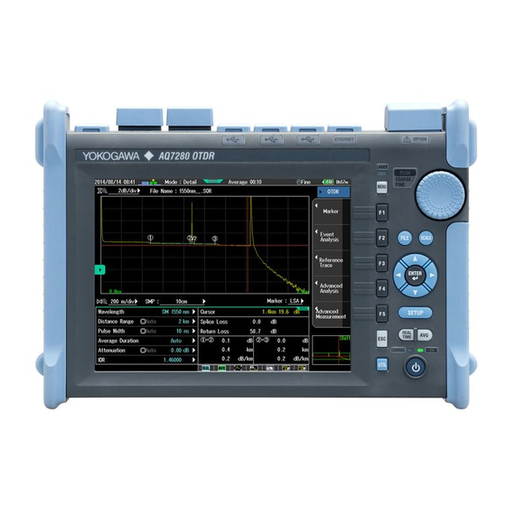
Common Operations Screen Explanation The OTDR screen will be used as an example to explain the screen interface. Battery level indicator Appears when the AC adapter is in use You can show and hide the SETUP If the AC adapter is not in use, menu by tapping the panel. - Page 52 Common Operations Soft Key Menu There are three types of soft key menus depending on the function. Pressing a soft key of a menu item with a frame confirms the selected item or executes its corresponding action. Pressing a soft key of a menu item with a mark displays a setup menu.
-
Page 53: Rotary Knob And Arrow Key Operations
Common Operations Rotary Knob and Arrow Key Operations We will use the dialog box that appears when you press the OPM Setup soft key as an example to explain the rotary knob and arrow key operations. Below are the different types of setup operations that you may encounter. Using the rotary knob or the up Pressing ENTER confirms the selected item or executes its corresponding action. -
Page 54: Touch Panel Operations
Common Operations Touch Panel Operations The basic touch panel operations are described below. Tap refers to the act of gently hitting the screen with your finger. Tapping is used on the AQ7280 screen to select areas with a mark, close a setup menu, and so on. - Page 55 Common Operations Where Touch Panel Operations Can Be Used Touch panel operations can be used in the following areas. In addition, touch panel operations can be used to zoom in and out. Drag Area with a mark Drag IM AQ7280-02EN...
-
Page 56: Setting The Date And Time
Common Operations Setting the Date and Time Press MENU to display the top menu. Press SETUP. Using the rotary knob and ENTER, select Date & Time Set to display the following screen. Set the year, month, and day. Set the hour, minute, and second. Set the AQ7280’s date and time to the specified values. -
Page 57: Entering Character Strings
Entering Character Strings After you have selected a setup item, a character input dialog box will appear if it is necessary. This section explains the operations that you can perform after the dialog box appears. Moves the cursor to the left Moves the cursor to the right Cursor Deletes the previous character... -
Page 58: Optical Pulse Measurement In Simple Mode
Optical Pulse Measurement in Simple Mode Configuring the Simple Mode Conditions In this mode, the absolute minimum amount of measurement conditions are set manually. You only have to set the wavelength. Conditions such as Distance Range, Pulse Width, and Event Search are set automatically when measurement starts. Select OTDR. -
Page 59: Performing Averaged Measurements
Optical Pulse Measurement in Simple Mode Performing Averaged Measurements In an averaged measurement, the data that is acquired from each pulse is averaged and displayed. When averaged measurement is performed, the signal-to-noise ratio rises. Averaged measurement is useful when you want to detect faint events that would normally be obscured by noise. - Page 60 Optical Pulse Measurement in Simple Mode Event Screen When Event Analysis is set to Auto, the event screen appears after averaged measurement ends normally. In the event screen, you can display the distance to each event and each event’s loss. Measurement reference point: S Event no.
-
Page 61: Analysis Using The Emulation Software
Analysis Using the Emulation Software The waveform data that is measured by the AQ7280 can be analyzed on your PC using the AQ7932 OTDR emulation software (version 5.01 or later). The software comes with a report creation wizard that is convenient in creating construction reports. IM AQ7280-02EN... -
Page 62: Specifications
Specifications AQ7280 OTDR Mainframe Item Specification Display 8.4 inch color TFT LCD (Multi-touch capacitive touchscreen) Total number of displayed pixels: 800 (horizontal) × 600 (vertical) pixels POWER (power supply ON/OFF display), CHARGE (charging condition), Laser (Laser emitting status) External I/F... - Page 63 Specifications OTDR Function Item Specification Minimum readout Horizontal axis: 1 cm, Vertical axis: 0.001 dB resolution Group refractive index 1.30000 to 1.79999 (in 0.00001 steps) Unit of distance km, mile, kft Backscatter level Selectable: PW = 1 µs or 1 ns Measurement functions Distance measurement, Loss measurement, Return loss measurement and Return loss measurement between any arbitrary points on the trace.
-
Page 64: Otdr Unit
Specifications OTDR Unit AQ7282A, AQ7083A, AQ7284A, AQ7285A Item Specifications Model AQ7282A AQ7283A AQ7284A AQ7285A Wavelength (nm) 1310 ± 25 / 1550 ± 25 Number of optical port Optical fiber SM (ITU-T G.652) Distance range (m) 0.2, 0.5, 1, 2, 5, 10, 20, 30, 50, 100, 200, 300, 400, 512 Pulse width (ns) 3, 10, 20, 30, 50, 100, 200, 300, 500, 1000, 2000, 5000, 10000, 20000 Sampling resolution... - Page 65 Specifications AQ7283F, AQ7283H, AQ7284H, AQ7283K, AQ7282M Item Specifications Model AQ7283F AQ7283H AQ7284H AQ7283K AQ7282M Wavelength (nm) 1310 ±25/ 1310 ±25/ 1310 ±25/ 850 ±30/ 1550 ±25, 1550 ±25/ 1490 ±25/ 1300 ±30 1650 ±5 ±10 1625 ±25 1550 ±25/ 1625 ±25 Number of optical port 2 (Port 2: 1650 nm with filter)
- Page 66 Specifications Item Specifications Model AQ7283F AQ7283H AQ7284H AQ7283K AQ7282M Maximum optical pulse output power +15 dBm or less – (1650 nm) Dimension 211 mm (W) × 110 mm (H) × 32 mm (D) (excluding projections) Mass Approx. 420 g Pulse width: 3 ns, Return loss: ≥55 dB, Group refractive index: 1.5, at 1.5 dB below the unsaturated peak level, Typical Pulse width: 10 ns, Return loss: ≥55 dB, Group refractive index: 1.5, at a point where the backscatter level is within ±0.5 dB of the normal level, Typical Pulse width: 20000 ns, Measurement time: 3 minutes, SNR = 1, Typical, Decrease by 0.5 dB with an angled-PC connector,...
- Page 67 Specifications AQ7283E, AQ7082G, AQ7283J Item Specifications Model AQ7283E AQ7282G AQ7283J Wavelength (nm) 1310 ±25/1550 ±25, 1310 ±25/1490 ±15/ 1310±25/1383±2/ 1625 ±10 1550 ±25 1550±25/1625±25 Number of optical port 2 (Port 2: 1625 nm with filter) Optical fiber SM (ITU-T G.652) Distance range (m) 0.2, 0.5, 1, 2, 5, 10, 20, 30, 50, 100, 200, 300, 400, 512 Pulse width (ns)
- Page 68 Specifications Optional functions for OTDR units Item Specifications AQ7282A AQ7283A AQ7284A AQ7285A Model Power checker (/PC) Wavelength setting 1310/1490/1550/1625/1650 nm Power range –50 to –5 dBm Measurement accuracy ±0.5 dB Optical input port OTDR port Stabilized light source Wavelength (nm) 1310 ±25/1550 ±25 (/SLS) Optical output power...
- Page 69 Specifications Item Specifications Model AQ7283E AQ7282G AQ7283J AQ7282M Power checker (/PC) Wavelength setting 1310/1490/1550/1625/1650 nm – Power range –50 to –5 dBm – Measurement accuracy ±0.5 dB – Optical input port OTDR port OTDR port – Stabilized light source Wavelength (nm) 1310 ±25/ 1310 ±25/ 1310 ±25/...
-
Page 70: Opm/Vls Modules
Specifications OPM/VLS modules Item Specifications Model AQ2780 AQ2781 AQ2780V AQ2781V AQ4780 High Power OPM OPM + VLS High Power OPM + VLS Optical power meter (OPM) Wavelength setting Mode: 850/1300/1310/1490/1550/1625/1650 nm, Detail mode: 800 to 1700 nm (1 nm steps), −... -
Page 71: General Specifications
Compliant Standard: EN61326-1 Table 2 (for use in industrial locations) Environmental Standard Compliant Standard: EN50581 Monitoring and control instruments including industrial monitoring and control instruments. Typical Power save mode, without an option module AQ7280 OTDR mainframe together with OTDR unit, OPM module, and VLS module. IM AQ7280-02EN... -
Page 72: External Dimensions
Specifications External Dimensions AQ7280 OTDR Mainframe Unit: mm (approx. inch) 6 (0.24) 287 (11.30) 6 (0.24) 80 (3.15) SIDE If not specified, the tolerance is ± 3%. However, in cases of less than 10 mm, the tolerance is ± 0.3 mm. - Page 73 Specifications OTDR unit (AQ7282A, AQ7283A, AQ7284A, AQ7285A, AQ7283E, AQ7283F, AQ7282G, AQ7283H, AQ7284H, AQ7283J, AQ7283K, AQ7282M) Unit: mm (approx. inch) 211 (8.31) 205.5 (8.09) If not specified, the tolerance is ± 3%. However, in cases of less than 10 mm, the tolerance is ± 0.3 mm. IM AQ7280-02EN...
- Page 74 Specifications Optical power meter module (AQ2780, AQ2780V, AQ2781, AQ2781V) 29 (1.14) 47 (1.85) When installed an Unit: mm universal adapter (SC). (approx. inch) VOID IF 16.3 (0.64) If not specified, the tolerance is ± 3%. However, in cases of less than 10 mm, the tolerance is ± 0.3 mm. IM AQ7280-02EN...
- Page 75 Specifications AQ4780 Visible light source module Unit: mm 29 (1.14) 47 (1.85) (approx. inch) VOID IF 16.3 (0.64) If not specified, the tolerance is ± 3%. However, in cases of less than 10 mm, the tolerance is ± 0.3 mm. IM AQ7280-02EN...
Need help?
Do you have a question about the AQ7280 OTDR and is the answer not in the manual?
Questions and answers