Table of Contents
Advertisement
Advertisement
Table of Contents

Related Manuals for METREL EasiTEST MI 2087 AL2


Summary of Contents for METREL EasiTEST MI 2087 AL2
- Page 1 EasiTEST MI 2087 AL2 Instruction Manual Version 1, Code No. 20 750 810...
- Page 2 Mark on your equipment certifies that this equipment meets the requirements of the EU (European Union) concerning safety and interference causing equipment regulations © 2003 METREL No part of this publication may be reproduced or utilized in any form or by any means without permission in writing from METREL.
-
Page 3: Table Of Contents
MI 2087 AL2 EasiTEST Table of conteents Introduction ......................4 General description..................4 Warnings......................4 List of parameters measurable by the EasiTest..........5 Standards applied..................6 Instrument description ..................7 Front panel..................... 7 Connector panel .................... 9 Bottom side....................10 Standard accessories .................. -
Page 4: Introduction
1 Introduction Congratulations on your purchase of the EasiTest test instrument and it's accessories, produced by METREL d.d. We are glad to offer high professional test equipment for carrying out absolute inspection of electrical installations in buildings. The equipment was designed and produced on basis of rich experiences, acquired through many years of dealing with electrical installation test equipment. -
Page 5: List Of Parameters Measurable By The Easitest
MI 2087 AL2 EasiTEST Introduction 1.3 List of parameters measurable by the EasiTest Parameter Switch Description position Insulation resistance INSULATION Test voltage: 250 V, 500 V, 1000 V Test current: > 200mADC Continuity resistance of protective conductors CONTINUITY Single measurement Auto polarity reverse Fault loop resistance R LOOP L-E,... -
Page 6: Standards Applied
MI 2087 AL2 EasiTEST Introduction 1.4 Standards applied Instrument operation: IEC / EN 61557-1 IEC / EN 61557-2 IEC / EN 61557-3 IEC / EN 61557-4 IEC / EN 61557-6 DIN VDE 100 BS 7671 – 16 edition Electromagnetic compatibility (EMC): EN 61326 Safety: IEC / EN 61010-1 (instrument) -
Page 7: Instrument Description
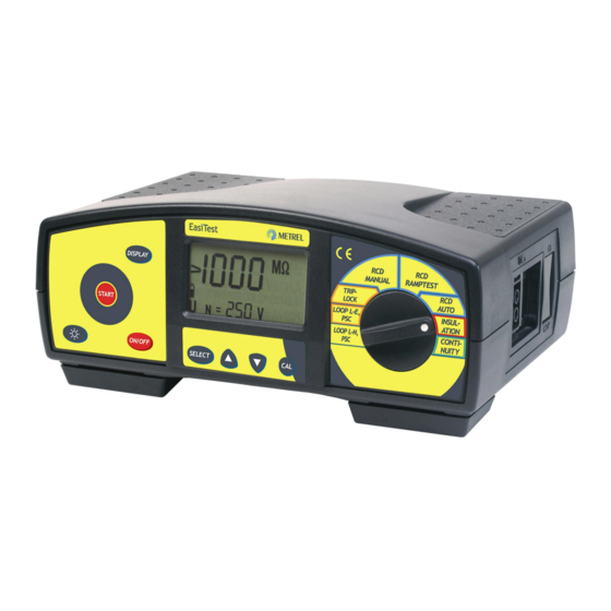
MI 2087 AL2 EasiTEST Instrument description 2 Instrument description 2.1 Front panel Fig. 1: Front panel... - Page 8 MI 2087 AL2 EasiTEST Instrument description Legend: 1 ..ON/OFF key, to switch ON or OFF the instrument. Auto OFF will occur automatically 10 minutes after any key is pressed or function switch rotated. 2 ..LAMP key, to turn ON or OFF display backlight. Auto OFF will automatically occur 20 seconds after to any key is pressed or function switch rotated.
-
Page 9: Connector Panel
MI 2087 AL2 EasiTEST Instrument description 2.2 Connector panel Use original test cables only! Max. allowed voltage between test terminals and ground is 300V! Max. allowed voltage between test terminals is 500V! Fig. 2: Connector panel Legend: 1..Main test connector... -
Page 10: Bottom Side
MI 2087 AL2 EasiTEST Instrument description 2.3 Bottom side Fig. 3: Bottom side Legend: 1 ..Nylon strip (it serves for carrying the instrument around the neck). 2 ..Auxiliary nylon strip (it serves for fixing the instrument around operator' body). 3 ..Plastic cover (it fixes nylon strip to the instrument). There is a screw under the cover which has to be unscrewed when opening the instrument for service or calibration purpose. -
Page 11: Standard Accessories
MI 2087 AL2 EasiTEST Instrument description 2.4 Standard accessories See attached sheet to compare received set of accessories with listed one. 2.5 Optional accessories See attached sheet to check the list of possible optional accessories which may be supplied upon request. 2.6 Ways of carrying the instrument As two carrying belts (neck and back) are supplied in standard set, various possibilites of carring the instrument are available. -
Page 12: Accessories Required For Specific Measurement
MI 2087 AL2 EasiTEST Instrument description 2.7 Accessories required for specific measurement The table below presents accessories (standard or optional) required for specific measurement. The accessories marked as optional may also be standard ones in some set configurations. Please see attached list of standard accessories for your set configuration or contact your dealer for further information. -
Page 13: Measurement Instructions
MI 2087 AL2 EasiTEST Measurement instructions 3 Measurement instructions 3.1 Insulation resistance There are different objects, where insulation resistance has to be measured in order to assure safety against electric shock. Let’s list a few examples: insulation resistance between installation conductors (all combinations) insulation resistance of non-conductive rooms (walls and floors) insulation resistance of ground cables resistance of semiconductive (antistatic) floors... - Page 14 MI 2087 AL2 EasiTEST Measurement instructions Step 2 Select nominal test voltage as follows: Press the SELECT key, last set nominal test voltage starts to blink. Fig. 5: Test voltage adjustment menu Use the ▲ and ▼ keys to set required nominal test voltage. The following values can be selected: 250V, 500V or 1000V.
-
Page 15: Continuity Of Protective Conductors
MI 2087 AL2 EasiTEST Measurement instructions Notes: In case that present external voltage higher than 29V (AC or DC) ia present between test terminals the insulation resistance measurement will not be carried out after pressing START key, but the voltage will be displayed, equipped with “!”... - Page 16 MI 2087 AL2 EasiTEST Measurement instructions Step 2 Compensate test leads (if they have not been compensated yet or, if already compensated test leads have been exchanged) as follows: Short test leads; see the figure below. N/L2 N/L2 PE/L3 PE/L3 L/L1 L/L1 Fig.
- Page 17 MI 2087 AL2 EasiTEST Measurement instructions PCC3 PCC1 Option A 1002 PCC2 MPEC Option A 1012 Fig. 10: Connection of optional Tip Commander (Order No. A 1002) and optional Probe Test Lead (Order No. A 1012) Step 5 Press the START key and release it. Measurement will be carried out and result displayed afterwards.
-
Page 18: Rcd - Contact Voltage And Fault Loop Resistance
MI 2087 AL2 EasiTEST Measurement instructions 3.3 RCD - Contact voltage and fault loop resistance For general information concerning Contact voltage / Fault loop resistance measurement refer to enclosed handbook Measurements on electric installations in theory and practice. How to carry out the measurement Step 1 Connect test cable (Universal test cable) to EasiTest. - Page 19 MI 2087 AL2 EasiTEST Measurement instructions Step 4 Select type of involved RCD as follows: Press the SELECT key after setting nominal differential current, last set type starts to blink. Select appropriate type using the ▲ and ▼ keys. Standard (General) type (G is displayed) or selective type (S is displayed) can be selected.
-
Page 20: Rcd - Trip-Out Time
MI 2087 AL2 EasiTEST Measurement instructions Step 8 (looP function is selected) Press the START key and release it, the measurement will start to run. Three dots (. . .) will flash until the measurement is finished, then the result is displayed. - Page 21 MI 2087 AL2 EasiTEST Measurement instructions How to carry out the measurement? Step 1 Connect test cable (Universal test cable) to EasiTest. Set function switch to RCD MANUAL position, Trip-out time initial menu will be displayed; see the figure below. G ..Standard (General) type of RCD is selected.
- Page 22 MI 2087 AL2 EasiTEST Measurement instructions Step 5 Connect test cable to tested object (mains outlet or other test terminals), according to the figure 12 (Universal test cable). Step 6 Press the START key and release it. Measurement will be carried out and result displayed afterwards (Trip-out time at set differential current).
-
Page 23: Rcd - Trip-Out Current
MI 2087 AL2 EasiTEST Measurement instructions 3.5 RCD – Trip-out current For general information concerning Trip-out current measurement, refer to enclosed handbook Measurements on electric installations in theory and practice. How to carry out the measurement? Step 1 Connect universal test cable to EasiTest. Set function switch to RCD RAMPTEST position, Trip-out current initial menu will be displayed;... -
Page 24: Rcd - Automatic Test
MI 2087 AL2 EasiTEST Measurement instructions Notes: If RCD trips during contact voltage measurement (some fault or leakage current is probably already flowing to ground), “rcd” mark will start to blink. Nominal differential current, set in this function, will be offered in other RCD functions (contact voltage, trip-out time and auto RCD test)! Limit contact voltage Ulim can be set in contact voltage function only! For safety reason will trip-out current measurement be carried out only, if... - Page 25 MI 2087 AL2 EasiTEST Measurement instructions Step 2 ∆n Select nominal differential current I as follows: Press the SELECT key, last set nominal differential current starts to blink. Select appropriate value using the ▲ and ▼ keys. The following values are available for selection: 10mA, 30mA, 100mA, 300mA or 500mA.
- Page 26 MI 2087 AL2 EasiTEST Measurement instructions test ∆ Trip-out time measurement, using test current Itest = I n/2, at negative start polarity of test current (180°). Tested RCD should not trip, the following display message will appear for a while: t2 ..
- Page 27 MI 2087 AL2 EasiTEST Measurement instructions Fig. 20: Fourth test is running (left figure), rcd message displayed after tripping out RCD (right figure) After reswitching RCD, fifth test will follow automatically. test ∆ Trip-out time measurement, using test current Itest = 5I n, at positive start polarity of test current (0°).
- Page 28 MI 2087 AL2 EasiTEST Measurement instructions Check partial results (trip-out times) separately for each step from 1 up to 6 as well as contact voltage at set nominal differential current (standard RCD type) or at double nominal differential current (selective RCD type) by using the DISPLAY key. If trip-out time in any step is out of allowed range (see the table 1) automatic test will be stopped and appropriate message will be displayed (>xxx ms / <xxx ms), where xxx means limit value according to the table 1.
-
Page 29: Fault Loop Resistance And Prospective Short-Circuit Current
MI 2087 AL2 EasiTEST Measurement instructions 3.7 Fault loop resistance and prospective short-circuit current For general information concerning the measurement, refer to enclosed handbook Measurements on electric installations in theory and practice. How to carry out the measurement Step 1 Connect test cable (Universal test cable) to EasiTest. -
Page 30: Line Resistance Rl-N/Rl-L And Prospective Short-Circuit Current
MI 2087 AL2 EasiTEST Measurement instructions Step 3 Press the START key and release it. Measurement will be carried out and result displayed afterwards. Check calculated prospective short-circuit current by pressing the DISPLAY key. The current is calculated as follows: Ipsc = Un⋅1.06 / R L-PE Where: (100V ≤... - Page 31 MI 2087 AL2 EasiTEST Measurement instructions Mains voltage not connected! Fig. 25: L-N(L) voltage and frequency measurement Check the frequency of mains voltage by pressing the DISPLAY key; see the figure above (right side). Step 2 Connect test cable to the tested object (mains outlet or other test terminals), according to the figure 24 (phase to neutral measurement) or according to the figure below (phase to phase measurement) .
- Page 32 MI 2087 AL2 EasiTEST Measurement instructions Notes: Nominal input voltage range is 100 V ÷ 440 V. If input voltage is out of the range, the voltage value equipped with “!” mark will be displayed after pressing START key. Warning sound is also emitted. If test result is out of display range, “>1999 Ω”...
-
Page 33: Other Operations
MI 2087 AL2 EasiTEST Other operations 4 Other operations 4.1 Reset of the instrument If any malfunction is noticed when dealing with the EasiTest, it is advisable to RESET the instrument. In that case all settable parameters will be set to their initial values; see the table below. -
Page 34: Maintenance
MI 2087 AL2 EasiTEST Maintenance 5 Maintenance 5.1 Batteries Disconnect test cable and switch off the instrument, before removing battery compartment cover! Hazardous voltage under the battery compartment cover! Battery condition is always displayed. See the battery condition indicator in the left side of the display. -
Page 35: Fuses
MI 2087 AL2 EasiTEST Maintenance Notes: Insert batteries correctly otherwise test instrument will not operate and batteries may be discharged; see figure 27 for correct battery polarity. 5.2 Fuses There are three fuses under battery compartment cover (see figure 27). F1 = M 0,315 A/250 V, 20×5 mm (It protects internal circuitry of the test instrument, if test tips are connected to mains voltage during the measurement of continuity of protective conductors by mistake). -
Page 36: Periodic Calibration
5.5 Service Repairs under or out of warranty time: Please contact your distributor for further information. Distributor’s address: Producer’s address: METREL d.d. Ljubljanska 77 SI-1354 Horjul tel.: +386 1 75 58 200 fax.: +386 1 7549 095 http://www.metrel.si E-mail: metrel@metrel.si... -
Page 37: Technical Specification
MI 2087 AL2 EasiTEST Technical specification 6 Technical specification 6.1 Functions *The accuracy is valid if: Insulation resistance Mains voltage is stabile during the meas. PE terminal is free of interfering voltage Resistance: Measuring range.........(0.008 ÷ 1000) MΩ Measurement principle ......without aux. probe Display range Resolution Test current ............<... -
Page 38: General Characteristics
MI 2087 AL2 EasiTEST Technical specification Voltage Uci: Measuring range........... (10 ÷ 100) V Line resistance and prospective short- Display range Resolution circuit current (LOOP L-N, PSC) Accuracy* (-0/+10) % of r. 0.00 ÷ 9.99 Line resistance RL-N(L): 0.01 ± 0.2 V Measuring range........
Need help?
Do you have a question about the EasiTEST MI 2087 AL2 and is the answer not in the manual?
Questions and answers