METREL MI 3125 Short Instructions
Eurotestcombo multifunction tester
Hide thumbs
Also See for MI 3125:
- Instruction manual (60 pages) ,
- Instruction manual (64 pages) ,
- Instruction manual (88 pages)

Related Manuals for METREL MI 3125


Summary of Contents for METREL MI 3125
- Page 1 EurotestCOMBO MI 3125 / MI 3125E Short instructions Version 2.2, Code no. 20 751 519...
- Page 2 Mark on your equipment certifies that this equipment meets the requirements of the EU (European Union) concerning safety and electromagnetic compatibility regulations © 2014 METREL No part of this publication may be reproduced or utilized in any form or by any means without permission in writing from METREL.
-
Page 3: Table Of Contents
MI 3125 / MI 3125E EurotestCOMBO Table of contents Table of contents Start-up guide ......................4 Safety and operational considerations ..............4 Instrument description - Front and connector panel ........... 5 Instrument description - Meaning of symbols ............. 5 Function selector switch and instrument display ..........7 Battery handling .................... -
Page 4: Start-Up Guide
MI 3125 / MI 3125E EurotestCOMBO Start-up guide 1 Start-up guide 1.1 Safety and operational considerations Warnings This document is not a supplement to the Instruction manual! symbol on the instrument means »Read the Instruction manual with special care for safe operation«. The symbol requires an action! If the test equipment is used in a manner not specified in this user manual, the ... -
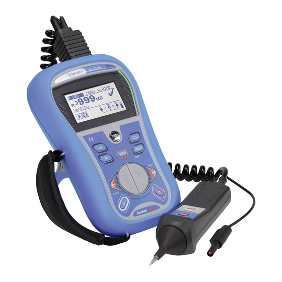
Page 5: Instrument Description - Front And Connector Panel
MI 3125 / MI 3125E EurotestCOMBO Start-up guide 1.2 Instrument description - Front and connector panel Instrument description 1. Display 2. TEST button 3. Arrow key 4. Arrow key 5. CAL button (for zeroing out leads, measuring Zref) 6. Function Selector 7. - Page 6 MI 3125 / MI 3125E EurotestCOMBO Start-up guide Message field – battery status Battery capacity indication. Low battery. Battery is too weak to guarantee correct result. Replace or recharge the battery cells. Recharging in progress (if power supply adapter is connected).
-
Page 7: Function Selector Switch And Instrument Display
MI 3125 / MI 3125E EurotestCOMBO Start-up guide 1.4 Function selector switch and instrument display Legend: 1. Function switch. 2. Function or sub-function name. 3. Measuring parameters and limit values. 4. Result field. In this field the main and sub-results together with the PASS/FAIL/ABORT status are displayed. -
Page 8: Maintenance
MI 3125 / MI 3125E EurotestCOMBO Start-up guide Power supply socket polarity Note: Only use the power supply adapter delivered from manufacturer or distributor of the test equipment to avoid possible fire or electric shock! 1.6 Maintenance 1.6.1 Replacing fuses Fuse M 0.315 A / 250 V, 20 x 5 mm... -
Page 9: Warranty & Repairs
Any shipping / return-shipping costs are not refundable. Metrel UK shall not be held liable for any loss or damage resulting from the use or performance of the products. In no event shall Metrel UK be liable to the customer... -
Page 10: Contact Metrel Uk
Metrel offers a repair service of all Metrel equipment. Contact Metrel UK on 01924 245000 and ask for the repairs department. Ask a technical question Metrel offers a Technical Advice Line every Mon-Thu from 8:00 a.m. till 5.00 p.m. and Fridays from 8:00 a.m. till 4 p.m. Get training on Metrel meters... -
Page 11: Quick-Test Guide
MI 3125 / MI 3125E EurotestCOMBO Quick-test guide 2 Quick-test guide 2.1 Null the leads Starting the tester: 1. Insert the fully charged batteries 2. Press the On/Off button 3. Connect test cable to the instrument. Step Select Continuity function with the function ... -
Page 12: Measurements
MI 3125 / MI 3125E EurotestCOMBO Quick-test guide 2.2 Measurements 2.2.1 Online Voltage and frequency / Phase sequence - AC Voltage measurement and frequency measurements, phase sequence Monitors voltages between L-N, L-PE and N-PE at the same time Values shown in real-time ... - Page 13 MI 3125 / MI 3125E EurotestCOMBO Quick-test guide View results Displayed results: Ul(1)-n(2): Voltage between phase and neutral conductors (or between phases L1 and L2) Ul(1)-pe(3): Voltage between phase and protective conductors (or between phases L1 and L3) Un(2)-pe(3): Voltage between neutral and protective conductors (or between ...
-
Page 14: Insulation Resistance - For Testing The Mω Value Of The Insulation Between Wires
MI 3125 / MI 3125E EurotestCOMBO Quick-test guide 2.2.2 Insulation resistance - For testing the MΩ value of the insulation between wires Test voltages can be changed from 50 V to 1000 V. Selectable limits can be set “on-screen” for quick evaluation of results. - Page 15 MI 3125 / MI 3125E EurotestCOMBO Quick-test guide TEST Press and hold the key until result has stabilised. View results Displayed results: R: Insulation resistance Um: Instrument test voltage...
-
Page 16: Continuity For Testing Resistance Of Earth Conductors And Equipotential Bonding
MI 3125 / MI 3125E EurotestCOMBO Quick-test guide 2.2.3 Continuity for testing resistance of earth conductors and equipotential bonding A limit can be set in order to automatically evaluate results. Results below the limit will be marked with a while results above the limit will be marked with a . - Page 17 MI 3125 / MI 3125E EurotestCOMBO Quick-test guide TEST Press the key. View results Displayed results: R: Main LowΩ resistance result R+: LowΩ resistance sub-result with positive voltage at L terminal R-: LowΩ resistance sub-result with positive voltage at PE terminal...
-
Page 18: Rcd Testing - 3 Functions For Testing Rcds
MI 3125 / MI 3125E EurotestCOMBO Quick-test guide 2.2.4 RCD testing - 3 functions for testing RCDs. For testing contact voltage on exposed earthed conductive parts. RCD t For testing the time it takes for an RCD to trip. - Page 19 MI 3125 / MI 3125E EurotestCOMBO Quick-test guide Connection diagram TEST Press the View results Displayed results: Uc: Contact voltage RL: Fault loop resistance Rmax: High limit fault loop resistance Displayed results: t: Tripping time Uc: Contact voltage Displayed results: IΔ: Tripping current...
-
Page 20: Loop - Fault Loop Impedance
MI 3125 / MI 3125E EurotestCOMBO Quick-test guide 2.2.5 Loop - Fault loop impedance Zloop High current loop test. Very quick and efficient for testing non RCD protected circuits. Zs rcd Low current loop test. Multitude of test performed over a longer period of time for increased accuracy. - Page 21 MI 3125 / MI 3125E EurotestCOMBO Quick-test guide TEST Press the View results Zloop Zs rcd Displayed results: Displayed results: Z: Fault loop impedance Z: Fault loop impedance Isc: Prospective fault current Isc: Prospective fault current Lim: High limit fault loop impedance...
-
Page 22: Line Impedance - (Phase-Neutral, Phase-Phase)
MI 3125 / MI 3125E EurotestCOMBO Quick-test guide 2.2.6 Line impedance - (phase-neutral, phase-phase) Zline Used for testing between phases on a single or 3 phase system e.g. testing (L to N, L1 to L2, L2 to L3 etc). - Page 23 MI 3125 / MI 3125E EurotestCOMBO Quick-test guide Connection diagram Zline ΔU - Voltage drop TEST Press the View results ΔU Zline Displayed results: Displayed results: ΔU….Voltage drop, Z: Line impedance …..Prospective short-circuit current, : Prospective short-circuit current Z……Line impedance at measured point, Lim: High limit line impedance value (if Zref…Reference impedance...
-
Page 24: Earthing Resistance (Mi 3125E)
MI 3125 / MI 3125E EurotestCOMBO Quick-test guide 2.2.7 Earthing resistance (MI 3125E) Main earthing arrangements, lightning systems, local earthings, etc can be verified with the earthing resistance test. Set function Set parameters and limits High limit resistance Ω sets limit off, 1 Ω ÷ 5 ...
Need help?
Do you have a question about the MI 3125 and is the answer not in the manual?
Questions and answers