Table of Contents
Advertisement
Advertisement
Table of Contents

Subscribe to Our Youtube Channel
Related Manuals for METREL MI 2094


Summary of Contents for METREL MI 2094
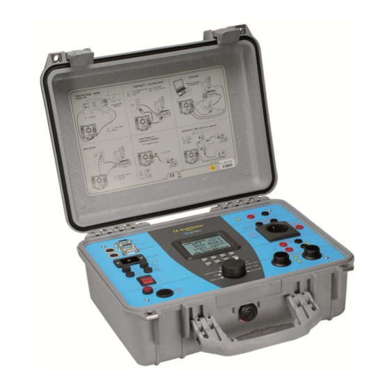
- Page 1 CE MultiTester MI 2094 User Manual Version 3.0, Code No. 20 751 557...
- Page 2 Mark on your equipment certifies that this equipment meets the requirements of the EU (European Union) concerning safety and interference causing equipment regulations © 2002…2009 METREL No part of this publication may be reproduced or utilized in any form or by any means without permission in writing from METREL.
-
Page 3: Table Of Contents
MI 2094 CE MultiTester Table of contents 1. General presentation ....................5 1.2. Warnings and notes ....................5 1.3. Warranty ....................... 6 1.4. List of measurements carried out by the instrument ..........7 1.5. List of applicable standards .................. 7 2. - Page 4 MI 2094 CE MultiTester Table of contents 6. Maintenance ......................64 6.1. Metrological check ....................64 6.2. Service ....................... 64 6.3. Cleaning ......................64 6.4. Replacing the fuses ( properly trained service personnel only!) ......64 7. PC Software - CE Link ..................... 66 7.1.
-
Page 5: General Presentation
MI 2094 CE MultiTester General presentation 1. General presentation 1.2. Warnings and notes In order to reach high level of operator’s safety while carrying out various tests and measurements using CE Multitester, as well as to keep the test equipment undamaged, it is necessary to consider the following general warnings: ... -
Page 6: Warranty
MI 2094 CE MultiTester General presentation Function test section Dangerous voltage is present on the TEST SOCKET (fig.1, pos.10) after pressing START/STOP push button. Power supply input Dangerous voltage is present on the fuses. Switch off the instrument and disconnect all test cables and mains cord before replacing the fuses or opening the instrument. -
Page 7: List Of Measurements Carried Out By The Instrument
MI 2094 CE MultiTester General presentation 1.4. List of measurements carried out by the instrument Withstanding programmed voltage - time sequence test Withstanding voltage test High voltage burn-out test Continuity test Voltage drop test Insulation resistance test ... -
Page 8: Description Of The Instrument
MI 2094 CE MultiTester Description of the instrument 2. Description of the instrument CE MultiTester RS232C MI2094 1000 V= WARNING LAMP 12 V~ / 0, 3 A EXT / DOOR IN DISCHARGING REMOTE TIME BAR-CODE READER 750 Vp CAT III 300 V... - Page 9 MI 2094 CE MultiTester Description of the instrument 15 ..SET key (press when the instrument is switched ON): Set date / time Set serial port settings Set barcode reader baud rate Clear records memory Clear devices / records ...
-
Page 10: Technical Specifications
MI 2094 CE MultiTester Technical specifications 3. Technical specifications 3.1. Withstanding test (PROG.HV and HV position) Nominal test voltage: ....adjustable 100 V÷ 5000 V / 50 Hz, 60 Hz at = 115 V / 230 V, P = 500 VA... -
Page 11: Burn Out (Hv Position)
MI 2094 CE MultiTester Technical specifications 3.2. Burn out (HV position) Selectable voltage ..........100 V÷ 5000 V Minimum burn out time before overheating: ..10 s I max.: ..............50 mA ÷ 60 mA 3.3. Low resistance (Continuity position) Resistance readout for currents 10 A and 25 A Measuring range according to EN 61557-4 is 0.011 ... -
Page 12: Voltage Drop Scaled To 10 A~ (Option In Continuity Position)
MI 2094 CE MultiTester Technical specifications Test voltage readout with currents 10 A and 25 A Range (V) Resolution (V) Accuracy (3 % of reading + 0.05 V) 0.000 – 10.000 0.001 Test voltage readout with currents 0.1 A and 0.2 A... -
Page 13: Insulation Resistance
MI 2094 CE MultiTester Technical specifications Max. output voltage: ....10 V Electronically stabilized current Current shape: ......sinusoidal Measuring current (external resistance of 0.0 - 0.5 connected to original test cable): ........>10 A Timer: ........adjustable 1 s - 59 s, resolution 1 s Connection system: .... -
Page 14: Substitute Leakage Current
MI 2094 CE MultiTester Technical specifications 3.7. Substitute leakage current Substitute leakage current readout: Range (mA) Resolution (mA) Accuracy (5 % of reading + 3 dig.) 0.00 – 20.0 0.01 Settable limits: ......0.1 mA – 20.0 mA (in step of 0.1 mA) Short circuit current: .... -
Page 15: Functional Test
MI 2094 CE MultiTester Technical specifications 3.9. Functional test Active Power, Apparent Power, Voltage, Current and Frequency monitoring on the test socket: Active Power, Apparent Power Range (W) Resolution (W) Accuracy (5 % of reading + 10 digit) 0 – 199.9 (5 % of reading + 3 digit) -
Page 16: Discharge Time (Disc.time Position)
MI 2094 CE MultiTester Technical specifications 3.10. Discharge time (DISC.TIME position) • Discharge time on power plug (external) Max. working voltage ......... 750V p Min. working voltage ........70 Vp, 140 V p Measuring range ........0 s - 10 s Resolution .......... - Page 17 MI 2094 CE MultiTester Technical specifications F2 ..F 5 A / 250 V (5 mm 20 mm) (general protection of the instrument) F3 ..T 16 A / 250 V (6.3 mm 32 mm) (test socket protection) F4 ..
-
Page 18: Measurements
MI 2094 CE MultiTester Measurements 4. Measurements 4.1. Withstanding test: Warning ! Disconnect all unused test leads before starting measurement; otherwise the instrument can be damaged! Only a skilled person, who is familiar with hazardous voltage operations, can perform this measurement! ... - Page 19 MI 2094 CE MultiTester Measurements i = i + i i ..absolute value of test current i ..capacitive current i ..resistive current -jIm Fig. 3. Test current diagram How to carry out the measurement STEP 1. Set rotary switch to HV (high voltage) position. The following heading is...
- Page 20 MI 2094 CE MultiTester Measurements Selected test voltage Fig. 5. Test voltage selection menu - Press Exit key to exit Test voltage selection menu. Trip-out current / character of displayed part of leakage current Press Ilim key in order to reach menu for trip-out current selection and character of displayed part of leakage current (resistive or capacitive).
- Page 21 MI 2094 CE MultiTester Measurements Timer value / timer OFF/ON Press Timer key and the menu for timer value selection is displayed. Use and keys to select appropriate test time value. To deactivate the timer press Toff key or Ton key to activate it. See the following figure.
- Page 22 MI 2094 CE MultiTester Measurements STEP 3. Connect test probes to the instrument as shown in figure below. Fig. 9. Connection of test probes STEP 4 . Close DOOR IN safety connector if enabled. (CONTINUITY test terminals have to be open).
-
Page 23: Withstanding Test With Preset Voltage/Time Diagram
MI 2094 CE MultiTester Measurements 4.2. Withstanding test with preset voltage/time diagram: WARNING ! Disconnect all unused test leads before starting measurement, otherwise the instrument can be damaged! Only a skilled person, who is familiar with hazardous voltage operations, can perform this measurement! ... - Page 24 MI 2094 CE MultiTester Measurements Fig. 11. Menu for programming ramp values Press Ilim key in order to reach menu for trip-out current selection and character of displayed part of leakage current (resistive or capacitive). The same procedure as for Ilim selection at HV function applies.
-
Page 25: Low Resistance Test With Currents Of 0.1A / 0.2A / 10A / 25A
MI 2094 CE MultiTester Measurements 4.3. Low resistance test with currents of 0.1A / 0.2A / 10A / 25A~ CONTINUITY position OBJECT UNDER TEST CE MultiTester MI2094 T EST U (0 - 230)V/(50, 60)Hz L OAD regulated Fig. 13. Test circuitry How to carry out the measurement STEP 1. - Page 26 MI 2094 CE MultiTester Measurements STEP 2. Select test parameters as follows: Measurement current Use In key to select appropriate measurement current. Resistance limit Press R key in order to reach the menu for selection of resistance limit (see the following figure).
- Page 27 MI 2094 CE MultiTester Measurements STEP 3. Connect test probes to the instrument and to the tested item as shown in the figure below. < 6 V/ (50, 60) Hz test > 0.1 A, 0.2 A, 10 A, 25 A...
-
Page 28: Voltage Drop Scaled To Test Current Of 10 A
MI 2094 CE MultiTester Measurements 4.4. Voltage drop scaled to test current of 10 A~ CONTINUITY position How to carry out the measurement STEP 1. Set rotary switch to CONTINUITY position, press Vdrop key. The following heading is displayed. Threshold voltage drop/wire section... -
Page 29: Insulation Resistance
MI 2094 CE MultiTester Measurements U: 0V...10V (scaled to 10A) < 6V/(50, 60)Hz test > 10A (for R : 0 m ...500 m ) test Fig. 19. Connection of test leads STEP 4. Press START/STOP key to start the measurement. - Page 30 MI 2094 CE MultiTester Measurements How to carry out the measurement STEP 1. Set rotary switch to ISO (insulation resistance) position, the following heading is displayed. Nominal test voltage Threshold insulation resistance Insulation resistance Measured test voltage Set timer value...
- Page 31 MI 2094 CE MultiTester Measurements Test voltage - Use Un key to select appropriate test voltage (250 V , 500 V , or 1000 V ). Timer value - See instructions on how to set the value in paragraph 4.1. STEP 2.
-
Page 32: Discharge Time - External (Input Mains Test)
MI 2094 CE MultiTester Measurements 4.6. Discharge time - external (input MAINS TEST) CE MultiTester MI2094 MAINS T ES T 230V/(50, 60)Hz Fig. 24. Test circuitry ideal power disconnection expected MAINS TEST moment input voltage 60 V, 120V discharge time power disconnection moment Fig. - Page 33 MI 2094 CE MultiTester Measurements How to carry out the measurement STEP 1. Set rotary switch to DISC.TIME (discharge time) position. The following heading is displayed. External measuring Limit values in external measurement Discharge time (main result) Present voltage peak...
-
Page 34: Discharge Time-Internal
MI 2094 CE MultiTester Measurements STEP 5. Press START/STOP key to prepare the instrument for switching off mains voltage. Ready is displayed after approx 1 s. Low Voltage message is displayed if the voltage on input mains is not appropriate (less than... - Page 35 MI 2094 CE MultiTester Measurements expected Line voltage Fig. 29. Expected voltage on tested object input possible TEST voltage 60 V, discharge time power disconnection moment Fig. 30. Expected voltage on discharge input How to carry out the measurement STEP 1.
- Page 36 MI 2094 CE MultiTester Measurements DIS CONNECT 0s...10s 0Vp...750Vp 60V , 120V 96M Fig. 31. Connection of test cables STEP 5. Press START/STOP key to prepare the instrument for switching off mains voltage. Ready is displayed after 1 s approx.
-
Page 37: Leakage Current
MI 2094 CE MultiTester Measurements 4.8. Leakage current CE MULTITESTER TEST OBJECT UNDER TEST SOCKET MI 2094 Fig. 32. Test circuitry How to carry out the measurement STEP 1. Set rotary switch to LEAK.CURRENT position. The following heading is displayed. -
Page 38: Subtitute Leakage Current
MI 2094 CE MultiTester Measurements Pmax = 3.5 kVA Fig. 34. Connection of tested object STEP 4. Press START/STOP key to start the measurement. STEP 5. Wait for the test time to elapse (if the timer has been switched on) or press START/STOP key again to stop the measurement. - Page 39 MI 2094 CE MultiTester Measurements Fig. 36. Heading in Substitute Leakage current function Set Leakage current limit - Press Ilim key to open menu to change leakage current limit value. - Use and keys to select appropriate limit value.
-
Page 40: Touch Leakage Current
MI 2094 CE MultiTester Measurements 4.10 Touch leakage current Touch leakage separated metal part TOUCH cca 2K Fig. 38. Touch Leakage test circuitry How to carry out the measurement STEP 1. Set rotary switch to LEAK.CURRENT position. STEP 2. Select test parameters as follows: Press Syst. -
Page 41: Functional Test
MI 2094 CE MultiTester Measurements Pmax = 3.5 kVA Fig. 40. Connection of tested object STEP 4. Press START/STOP key to start the measurement. STEP 4. Touch ungrounded metal part by using test probe. STEP 5. Wait for the test time to elapse (if the timer has been switched on) or press START/STOP key again to stop the measurement. - Page 42 MI 2094 CE MultiTester Measurements Values related to tested object Apparent power threshold value Tested object current Line voltage Active power Apparent power Frequency Power factor Timer key to set timer value or to switch it on/off Limit key to set limit value Fig.
-
Page 43: Autotest
MI 2094 CE MultiTester Measurements 4.12. Autotest Autotest is a very powerful tool, which is constructed to make the process of measurement easier, more flexible or even automatic. It gives an assurance that the complete measurement procedure is carried out. Any previously designed sequence by CE Link software (up to 10 sequences, each composed of up to 50 steps can be saved in CE MultiTester memory) will be executed step by step. - Page 44 MI 2094 CE MultiTester Measurements How to carry out the measurement STEP 1. Install CE Link PC software on your PC. STEP 2. Using Sequence editor, create the desired sequence. Max. number of steps for each sequence is 50 including programmed pause, messages, barcode reader sequence, sound signals etc.
- Page 45 MI 2094 CE MultiTester Measurements Press View key view sequence steps Fig. 46. Sequence name is displayed, to display individual steps press View key STEP 5. Press START/STOP key to start the measurements that compose the sequence. Note! Keep the rotary switch unmoved until the execution of autotest sequence is...
- Page 46 MI 2094 CE MultiTester Measurements STEP 10. WAIT FOR EXTERNAL INPUT sequence will be continued after external impulse. STEP 11. DISCHARGE Internal {U: 60 V; t: 5 s}. STEP 12. MESSAGE {LEAK.: L to PE; FUNCT.} (notice to prepare device for DISCH test and after PAUSE for FUNCT.
- Page 47 MI 2094 CE MultiTester Measurements...
-
Page 48: Operation
MI 2094 CE MultiTester Operation 5. Operation 5.1. Warnings Different warnings or information can be reported during manipulation with the CE MultiTester. Here is a list of warnings and information for each function. HV and PROG.HV function: Trip out ......The HV generator tripped-out due to the test current, which was higher than the set limit value. -
Page 49: Results Memory
MI 2094 CE MultiTester Operation General: HOT ....The instrument is overheated (CONTINUITY, VOLT.DROP, HV and PROG.HV); sign is also displayed. Fig. 47. Example of hot message Measurements in functions ISO, LEAK.CURRENT, FUNCTION. TEST and DISC.TIME can still be carried out. - Page 50 MI 2094 CE MultiTester Operation How to save displayed results The displayed result can be saved only after the measurement is complete. STEP 1. Carry out the measurement. STEP 2. Press MEM key in order to reach memory menu for saving results (see fig.
-
Page 51: Recalling Of Stored Results
MI 2094 CE MultiTester Operation 5.3. Recalling of stored results The results can be recalled only before the measurement is performed or after the result is saved. STEP 1. Press MEM key in order to reach memory menu for recalling results (see fig. -
Page 52: Communication
MI 2094 CE MultiTester Operation 5.4. Communication In order to transfer stored data to PC, USB and/or RS 232 communication feature shall be used. See 5.5. System configuration for communication set-up. 5.4.1. RS232 interface Fig. 52. RS 232 communication cable... -
Page 53: System Configuration
MI 2094 CE MultiTester Operation STEP 4. Use and keys to select one of displayed options and press Enter key. STEP 5. After pressing Enter key the selected function submenu is displayed at the bottom of menu: 5.5. System configuration To reach System configuration menu the following procedure must be carried out: STEP 1. - Page 54 MI 2094 CE MultiTester Operation SERIAL COMMUNICATION PORT set-up: Use Mode key to select between USB and RS232. Use Sel. key to select appropriate baud rate from 9600, 19200 or 38400. After exit, the selected communication port and new baud rate will be confirmed and basic menu is displayed.
- Page 55 MI 2094 CE MultiTester Operation LOAD DEFAULT SETTING Sets all adjustable test parameters to their initial values. Press Enter key to confirm or Exit key to exit. INPUT DOOR IN: Enables or to disables DOOR IN input. After selecting this option press Enter to switch...
- Page 56 MI 2094 CE MultiTester Operation Function Parameter Range of adjustment or possible Initial value values test current 10 A 100 mA, 200 mA, 10 A, 25 A (10 - 990) m (by steps of 10 m) (1000 - max. allowed Continuity 2000) m...
-
Page 57: Contrast Of The Display
MI 2094 CE MultiTester Operation 5.6. Contrast of the display Where there is insufficient readability of the display (display too dark or intensity of messages too weak), the appropriate contrast of the display should be set. How to set appropriate contrast It is possible to adjust contrast in all positions of main switch. - Page 58 MI 2094 CE MultiTester Operation Fig. 56. Connection of remote control pedal to CE MultiTester Note! The selected contrast may change due to a change in temperature of the display (instrument heat or changed ambient temperature).
-
Page 59: Use Of Warning Lamp
MI 2094 CE MultiTester Operation How to operate REMOTE CONTROL pedal START/STOP function on the pedal is exactly the same as on front panel of the instrument when the pedal is not connected. SAVE function on the pedal is automatic, so a double press to SAVE pedal is required to save displayed result to the next location of set device number. -
Page 60: Use Of Barcode Reader
MI 2094 CE MultiTester Operation READY Instrument connector TEST (female) type MAB 5100 DIN 41524 (front view) 12V DC and internal instrument circuitry front view Fig. 57. Connection of warning lamp to CE MultiTester Technical specifications of the WARNING LAMP: ... -
Page 61: Use Of Ext/Door Input
MI 2094 CE MultiTester Operation 5.10. Use of EXT/DOOR input Specification of EXT. / DOOR IN signals: Pin 2: Pass / Fail (digital output) Pin 3: External input (digital input) Pin 4: Next test (digital output) Pin 5: Door in... - Page 62 MI 2094 CE MultiTester Operation PASS / FAIL: In autotest and individual measurements the status of measurement (PASS / FAIL) is given on pin 2 of EXT / DOOR IN connector. If the measurement result is inside the range of limit then pin 2 is HI level. If the measurement is out of limit range then pin 2 is LO level.
- Page 63 MI 2094 CE MultiTester Operation Application example – unpredictable pause time for the same action (manual action is part of preparation for another measurement). Next test: Pin 4 indicates the end of execution of each measurement (change from LO to HI).
-
Page 64: Maintenance
MI 2094 CE MultiTester Maintenance 6. Maintenance 6.1. Metrological check It is essential that all measurement instruments are regularly calibrated. We recommend an annual calibration to be carried out. 6.2. Service Repairs under or out of guarantee: Please return the products to your distributor. - Page 65 MI 2094 CE MultiTester Maintenance Manufacturer address: METREL d.d. Ljubljanska 77, SI-1354 Horjul Tel: +(386) 1 75 58 200 Fax: +(386) 1 75 49 095 Email: metrel@metrel.si The instrument contains no user serviceable parts. Only an authorized dealer is allowed to carry out service...
-
Page 66: Pc Software - Ce Link
MI 2094 CE MultiTester PC Software - CE Link 7. PC Software - CE Link 7.1. Installing CE Link CE Link software is 32-bit application for Windows platforms. Before installing CE Link it is recommended to close all running programs on your PC. - Page 67 MI 2094 CE MultiTester PC Software - CE Link Fig. 63 Code settings window Basic screen is start point for all actions. Fig. 64. Basic screen...
-
Page 68: Download Data
MI 2094 CE MultiTester PC Software - CE Link Download data: Port settings: Opens window for downloading or auto - Opens window for port and downloading data from baud rate settings. CE MultiTester to PC. Shortcut key: Shortcut key: Alt S + P... - Page 69 MI 2094 CE MultiTester PC Software - CE Link Fig. 65. Port settings window Check baud rate on CE MultiTester by using SET key (see SERIAL PORT BAUD RATE setup in SYTEM CONFIGURATION in chapter 5.5) Prepare CE MULTITESTER for communication by pressing RS232 key (instrument will go in communication mode).
- Page 70 MI 2094 CE MultiTester PC Software - CE Link Fig. 67. Downloading data windows For auto download from instrument (instrument must be in the Autotest mode) choose AutoReceive download option. In this mode PC waits to receive record from the instrument. Instrument sends record to the PC at the end of each sequence procedure.
-
Page 71: Open Data File
MI 2094 CE MultiTester PC Software - CE Link Before starting of the autotest you should press Start button in the Auto receive mode window. There is a counter for the number of received records since Start pressed. ... - Page 72 MI 2094 CE MultiTester PC Software - CE Link Fig. 71. Data file window In the table all failed measurements will be marked by red color. By using search button (see table 2) the user can easily jump from one to another failed measurement.
-
Page 73: Printing Documents
MI 2094 CE MultiTester PC Software - CE Link Delete: Export to clipboard: Deletes selected row (after Exports selected rows on delete paste is not available). clipboard. Shortcut key: Shortcut key: Alt E Delete, Alt E + S Mark / Unmark row:... - Page 74 MI 2094 CE MultiTester PC Software - CE Link Header options define header height, include bitmap file (user logo - in our example windows clouds.bmp), underline header, write header text (first line above bitmap, other five under),...
-
Page 75: Print Separately
MI 2094 CE MultiTester PC Software - CE Link Fig. 73. PRINT preview 7.5.2 Print separately Print separately function prints each measured device results to its own document. It is intended to print separate reports for each tested object (production line testing). -
Page 76: Header Programming
MI 2094 CE MultiTester PC Software - CE Link 7.6. Header programming Fig. 74. Header programming window This window represents info window for your instrument (called header). To see instrument header the instrument has to be connected to PC. User can change “User string” (max 48 characters), send system time (time and date set on the PC). -
Page 77: Sequence Editor
MI 2094 CE MultiTester PC Software - CE Link 7.7. Sequence editor Basic point of Sequence editor is displayed in chapter 4.10. AUTOTEST. The user will use Sequence editor to create desired sequences or to edit existing sequence on the instrument. - Page 78 MI 2094 CE MultiTester PC Software - CE Link Voltage drop Parameter window Continuity Current Parameter window High Voltage Parameter window Programmed High Voltage Parameter window...
- Page 79 MI 2094 CE MultiTester PC Software - CE Link Insulation Parameter window Sound Parameter window Pause Parameter window Leakage Current Parameter window Message Parameter window Fig. 76. Parameter windows To set program name in Command table select Program settings. In this dialog box user can also enable: - pause (0 s –...
- Page 80 MI 2094 CE MultiTester PC Software - CE Link Fig. 77. Program name – definition window Created sequence can be sent to CE MultiTester, and saved to disc with extension SQC. List of instrument Clear row data: programs: Clears only data, not whole Reads, delete and sends row.
Need help?
Do you have a question about the MI 2094 and is the answer not in the manual?
Questions and answers