
Subscribe to Our Youtube Channel
Related Manuals for wtw DIQ/S 182-PR


Summary of Contents for wtw DIQ/S 182-PR
- Page 1 System operating manual DIQ/S 182-PR (System 182) Modular measuring system for 2 digital sensors with PROFIBUS-DP output ba75503e07 04/2012...
- Page 2 The latest version of the present operating manual can be found on the Internet under www.WTW.com. © Copyright Weilheim 2012, WTW GmbH Reprinting - even as excerpts - is only allowed with the explicit written authorization of WTW GmbH, Weilheim. Printed in Germany. ba75503e07 04/2012...
-
Page 3: Table Of Contents
3.8.1 DIQ/S 182-PR (Line power version) ....... . . 3-29 3.8.2... - Page 4 Contents System 182 Operation ............4-1 Operating elements .
- Page 5 10.1 DIQ/S 182-PR ........
- Page 6 Contents System 182 0 - 4 ba75503e07 04/2012...
-
Page 7: Overview
Structure and function The System 182 is a modular, multiparameter measuring system. The control and operation unit of the system is the DIQ/S 182-PR Universal Transmitter with integrated power pack. Is has three relay outputs and a PROFIBUS-DP output for the connection to existing process control systems. - Page 8 (PROFIBUS-DP) and thus a connection to a superordinate process control. Compressed air-driven The DIQ/S 182-PR Universal Transmitter is prepared for the cleaning system compressed air-driven, time-controlled sensor cleaning function. For this, a DIQ/CHV valve module and if necessary a CH cleaning head is required per sensor (both available as accessories).
-
Page 9: Behavior Of The System In The Case Of Power Failure
System 182 Overview Behavior of the system in the case of power failure The system configuration remains stored permanently. It consists of the following settings: – Sensor settings – Settings and links of relay outputs – PROFIBUS settings – System settings (display language, air pressure/location altitude, passwords, etc.) ... - Page 10 Overview System 182 1 - 4 ba75503e07 04/2012...
-
Page 11: Safety Instructions
System 182 Safety instructions Safety instructions This operating manual contains essential instructions that must be followed during the commissioning, operation and maintenance of the System 182. Thus, it is essential for the operator to read this component operating manual before carrying out any work with the system. -
Page 12: Authorized Use
The following installation activities may only be performed by a qualifications qualified electrician: Connecting the DIQ/S 182-PR Universal Transmitter or an additional MIQ power supply module to the power supply. Connecting external, line voltage-carrying circuits to relay contacts. - Page 13 System 182 Safety instructions Safe operation If safe operation is no longer possible, the System 182 must be taken out of operation and secured against inadvertent operation. Safe operation is no longer possible if components: have been damaged in transport ...
- Page 14 Safety instructions System 182 2 - 4 ba75503e07 04/2012...
-
Page 15: Installation
System 182 Installation Installation Note How to connect the DIQ/S 182-PR to the PROFIBUS master is described in detail in the chapter 7 PROFIBUS CONNECTION Scope of delivery The following parts are included in the scope of delivery of the DIQ/ S 182-PR: ... - Page 16 Installation System 182 The external protective measures of the installation environment can be carried out with respect to the following guidelines: 1 All lines of the IQ S system must be ENSOR a) installed inside (or else close to) the grounded metallic mounting constructions, e.g.
- Page 17 System 182 Installation with overvoltage category II. Generally this is ensured through the public operator of the power supply networks. In company-owned networks, e.g. in all power supply systems owned by wastewater treatment plants, this must be kept separate by a potential equalization and a surge protection system for the plant.
-
Page 18: Connecting System Components
The back of the Universal Transmitter or an MIQ module is attached to the lid of an MIQ module (page 3-6). DIQ/S 182-PR Select this variant if an MIQ Module MIQ module is already permanently installed, e.g. to a wall. - Page 19 System 182 Installation Caution For optimum stability, a maximum of two MIQ modules may be connected to the Universal Transmitter. One MIQ power supply module only may be mounted per stack in addition to the Universal Transmitter. Note In the case of panel mounting, the front module must be installed individually in the switch cabinet aperture first.
-
Page 20: Variant 1: Stack Expansion Forwards
Installation System 182 3.4.2 Variant 1: Stack expansion forwards Preparing the stack mounting MIQ module DIQ/S 182-PR t a p t f e e lm r n e t a g u f k n t ie n t a... - Page 21 Transmitter with the two plastic tapping screws (pos. 6). On the Universal Transmitter, remove the two countersunk screws (pos. 7 in Fig. 3-2) and swing open the lid. Premounting the ISO DIQ/S 182-PR blind nuts Fig. 3-3 Premounting the ISO blind nuts (variant 1) Insert the cheese-head screws (pos.
- Page 22 Installation System 182 Stacking the MIQ modules MIQ module DIQ/S 182-PR Fig. 3-4 Stacking the MIQ modules (variant 1) MIQ module DIQ/S 182-PR Fig. 3-5 Closing the enclosure (variant 1) Attach the prepared Universal Transmitter to the lid of the MIQ module.
-
Page 23: Variant 2: Stack Expansion Backwards
System 182 Installation 3.4.3 Variant 2: stack expansion backwards Preparing the stack MIQ module DIQ/S 182-PR mounting t a p t f e e lm r n e t a g u f k n t ie n t a... - Page 24 Installation System 182 Note Only use the plastic tapping screws supplied for attaching the contact base. They ensure the correct fit. Attach the contact base (pos. 6 in Fig. 3-7) on the Universal Transmitter with the two plastic tapping screws (pos. 7). Premounting the ISO MIQ module blind nuts...
- Page 25 System 182 Installation Stacking the MIQ modules MIQ module DIQ/S 182-PR Fig. 3-9 Stacking the MIQ modules (variant 2) DIQ/S 182-PR MIQ module Fig. 3-10 Closing the enclosure (variant 2) Attach the prepared MIQ module to the back of the Universal Transmitter.
-
Page 26: Distributed Mounting
Installation System 182 3.4.4 Distributed mounting General information For the locally separated connection between Universal Transmitter and MIQ modules and between MIQ modules the following cables can be used: SNCIQ cable SNCIQ/UG earth cable - suitable for underground laying in accordance with VDE 01816, Part 2 and DIN/VDE 0891, Part 6. - Page 27 System 182 Installation Preparing the cable Cut off the cable to the required length. ends Remove approx. 45 mm of cable insulation (in the case of the SNCIQ/UG earth cable, remove both the inner and outer insulation). Only for the SNCIQ/UG earth cable: strip the outer insulation for a further 35 mm.
- Page 28 Installation System 182 SENSORNET 1 SENSORNET 2 SNCIQ SACIQ SNCIQ/UG Fig. 3-12 Connecting cables (example of Universal Transmitter) Screw a cable gland (pos. 1 in Fig. 3-12) with the sealing ring (pos. 2) into the enclosure. Loosen the coupling ring (pos. 3 in Fig. 3-12). Feed the cable through the cable gland into the enclosure.
- Page 29 System 182 Installation Terminal labeling: SENSORNET 1 Filler stranded wire (SNCIQ...) or black (SACIQ) green SNCIQ(/UG) or SACIQ Fig. 3-13 Example: SENSORNET connection Connect the cable ends to the terminal strip. At the same time, look out for the designations of the terminals (red / shield / green).
-
Page 30: Connecting Iq Sensors
System 182 3.4.5 Connecting IQ sensors Sensors can be connected to all free SENSORNET connectors in the 182 system. The Universal Transmitter DIQ/S 182-PR has two SENSORNET connections. General installation Observe the following points when attaching sensors to the system: instructions ... - Page 31 System 182 Installation SACIQ Fig. 3-14 Connecting the SACIQ cable with the IQ sensor Note For further instructions on the mounting of IQ sensors at the application location, please see the respective manuals (immersion depths, etc.). ba75503e07 04/2012 3 - 17...
-
Page 32: On Site Mounting Of The Universal Transmitter And Miq Modules
On site mounting of the Universal Transmitter and MIQ Modules 3.5.1 General information The DIQ/S 182-PR and the DIQ and MIQ modules have a comprehensive program of mounting accessories, which can be used to adapt the installation to the most varied requirements. -
Page 33: Mounting On A Mounting Stand With The Ssh/Iq Sun Shield
System 182 Installation 3.5.2 Mounting on a mounting stand with the SSH/IQ sun shield SSH/IQ sun shield (see chapter 11 A Materials required CCESSORIES AND OPTIONS 4 mm set screw wrench Tools Phillips screwdriver. Mounting the sun shield on a mounting stand Fig. - Page 34 Installation System 182 Premounting the ISO blind nuts Fig. 3-16 Mounting the sun shield: Premounting the ISO blind nuts Remove the two countersunk screws (pos. 5 in Fig. 3-16) and swing open the lid. Insert the cheese-head screws (pos. 6 in Fig. 3-16) with the plastic washers in the drilled mounting holes and loosely screw in the ISO blind nuts (pos.
- Page 35 System 182 Installation Mounting the Universal Transmitter on the sun shield Fig. 3-17 Mounting the Universal Transmitter on the SSH/IQ sun shield Position the Universal Transmitter on the sun shield and fix it into place with the two screws (pos. 6 in Fig. 3-16). Close the lid and fix it with the two countersunk screws (pos.
-
Page 36: Panel Mounting
Installation System 182 3.5.3 Panel mounting PMS/IQ kit for panel mounting (see chapter 11 A Materials required CCESSORIES AND OPTIONS 3 mm set screw wrench (contained in the panel installation kit). Tools Switch panel aperture Maximum thickness 3 mm 34.5 Fig. - Page 37 System 182 Installation Mounting the Universal Transmitter in the panel le b u f k r ä g t a g k t t n t a e lm r e n t a p e la n t ie r n e ie r t f e...
-
Page 38: Top Hat Rail Mounting
Installation System 182 3.5.4 Top hat rail mounting THS/IQ kit for top hat rail mounting (see chapter 11 A Materials required CCESSORIES AND OPTIONS Phillips screwdriver. Tools Mounting the Universal Transmitter on a top hat rail le b u f k r ä... -
Page 39: Using Diq Modules (Accessories)
System 182 Installation Using DIQ modules (accessories) Note The various application possibilities of the DIQ modules are shown by means of examples in section 3.11. 3.6.1 DIQ/JB The DIQ/JB module is a passive branching module and can be used for the following purposes ... -
Page 40: Installation Of The Modules
3.6.3 Installation of the modules The DIQ module enclosure is designed like a commercial connection socket and can be mounted directly on a wall. For mounting on a WTW mounting stand, WTW provides the MS/DIQ mounting set. It contains a pipe clip for the mounting stand and provides enough space for two DIQ modules. -
Page 41: Electrical Connections: General Instructions
Cable glands All electric cables are fed from below via prepared openings in the enclosure of the DIQ/S 182-PR and the MIQ modules. Cable glands with different clamping ranges are included with the DIQ/S 182-PR to provide sealing between the cable and enclosure as well as for strain relief. - Page 42 Otherwise, there is a danger that areas safe to contact could come into contact with dangerous voltages. This could result in life threatening electric shock when working with the DIQ/S 182-PR. Always cut off any wires that are not in use as closely as possible to the cable gland.
-
Page 43: Connecting The Voltage Supply
Note The two following paragraphs describe how to connect both models of the DIQ/S 182-PR Universal Transmitter to the voltage supply. How to connect additional power supply modules is described in the operating manual of the respective power supply module. - Page 44 Installation System 182 Preparing the power Cut off the cable to the required length. cable Strip the cable insulation for approx. 45 mm. Bare the wires of phases L and N and fit them with wire end sleeves. If present, cut off the ground wire at the end of the cable sheath.
- Page 45 System 182 Installation Connecting the power Open the enclosure of the Universal Transmitter. line Fig. 3-26 Inserting the supply line. Screw a cable gland (pos. 1 in Fig. 3-26) with sealing ring (pos. 2) into the enclosure below the power supply connection. Loosen the coupling ring (pos.
- Page 46 Installation System 182 Terminal labeling: 100... 240V AC NETZ/MAINS Fig. 3-27 Line power connection. Note The complete assignment of the terminal strip is shown in section 3.12. Connect phases L and N to the terminal strip. Make sure that the cable assignment agrees with the specification on the terminal label under the terminal strip.
-
Page 47: Diq/S 182-Pr/24V (24 V Version)
System 182. The interrupt facility must – be installed in the vicinity of the DIQ/S 182-PR Universal Transmitter, easily accessible by the user, and – be labeled as the interrupt facility for the DIQ/S 182-PR Universal Transmitter. - Page 48 Installation System 182 ca. 45 mm wire 1 wire 2 Fig. 3-28 Prepared 24 V AC/DC line. Connecting the 24 V AC/ Open the enclosure of the Universal Transmitter. DC line Fig. 3-29 Inserting the 24V AC/DC line Screw a cable gland (pos. 1 in Fig. 3-29) with sealing ring (pos. 2) into the enclosure below the 24 V AC/DC connection.
- Page 49 System 182 Installation Terminal labeling: 24V AC DC EINGANG INPUT POWER Fig. 3-30 24 V AC/DC connection. Note The complete assignment of the terminal strip is shown in section 3.12. Connect wires 1 and 2 to the terminal strip. Make sure that the cable assignment agrees with the specification on the terminal label under the terminal strip.
-
Page 50: Additional Miq Power Supply Modules
Installation System 182 3.8.3 Additional MIQ power supply modules The power pack of the Universal Transmitter supplies enough power for most combinations of sensors. Some sensors with high power consumption may require the installation of an MIQ power supply module in addition to the Universal Transmitter. For installation, refer to the operating manual of the power supply module. - Page 51 System 182 Installation 2nd sensor 1st sensor ® TriOxmatic 700 IQ (SW) ® TriOxmatic 701 IQ ® TriOxmatic 702 IQ FDO 70x IQ (SW) ® TetraCon 700 IQ (SW) ® AmmoLyt 700 IQ ® NitraLyt 700 IQ Plus VARiON 700 IQ (with NH4-N or NO3-N) ®...
-
Page 52: Connections To The Relay Outputs
Installation System 182 Connections to the relay outputs 3.9.1 General installation instructions Warning If external electrical circuits that are subject to the danger of physical contact are incorrectly connected to the relay contacts, there may be a danger of life threatening electric shock. Electrical circuits are regarded to be subject to the danger of physical contact when there are voltages higher than the Safety Extra Low Voltage (SELV). - Page 53 System 182 Installation Connecting lines to the Open the enclosure of the Universal Transmitter. terminal strip Fig. 3-31 Inserting lines Note The complete assignment of the terminal strip is shown in section 3.12. Screw a cable gland (pos. 1 in Fig. 3-31) with the sealing ring (pos.
-
Page 54: Usage Of The Auxiliary Voltage
Caution The auxiliary voltage must not be used for other purposes. Connection scheme for one sensor with compressed air cleaning Terminal strip HILFS- SPANNUNG AUXILIARY DIQ/S 182-PR VOLTAGE Valve control line Terminal strip DIQ/CHV VERTEILER VENTIL DISTRUBUTION... - Page 55 System 182 Installation Caution Run the bridge below the divider so the bridge does not bump against the circuit board in the lid when the enclosure is closed. Separating plate Relais contact Auxiliary voltage output Bridge Valve control line Note Installation examples with one and two sensors with compressed air cleaning can be found in section 3.11.
-
Page 56: Commissioning
Installation System 182 3.10 Commissioning Start checklist and Before starting the system, carry out the system check using the system start following checklist. Always carry out the check before the initial commissioning before any further commissioning if the system has been previously extended or modified. -
Page 57: Installation Examples
System 182 Installation 3.11 Installation examples 3.11.1 Connecting two sensors without compressed air cleaning Max. total cable length SNCIQ(/UG) and SACIQ = 250 m DIQ/S 182-PR(/24V) DIQ/S 182-PR(/24V) SNCIQ(/UG) SNCIQ(/UG) DIQ/JB SACIQ SACIQ SACIQ Sensor 2 Sensor 1 Sensor 2 (distance >... -
Page 58: Connecting Two Sensors With Compressed Air Cleaning
Installation System 182 3.11.2 Connecting two sensors with compressed air cleaning Max. total cable length DIQ/S 182-PR(/24V) SNCIQ(/UG) and SACIQ = 250 m Valve control line 1 Valve control line 2 DIQ/CHV 2 DIQ/CHV 1 SACIQ SACIQ Sensor 2 Sensor 1... - Page 59 System 182 Installation Variant Terminal strip HILFS- HILFS- SPANNUNG SPANNUNG AUXILIARY AUXILIARY DIQ/S 182-PR VOLTAGE VOLTAGE X11 X10 X11 X10 Valve control line 1 Terminal strip DIQ/CHV 1 VERTEILER VENTIL DISTRUBUTION VALVE Valve control line 2 Terminal strip DIQ/CHV 2...
-
Page 60: Figures Of The Terminal Strips
Installation System 182 3.12 Figures of the terminal strips DIQ/S 182-PR £ £ £ 240V AC 240V AC 240V AC £ £ £ 2A AC 2A AC 2A AC HILFS- SPANNUNG AUXILIARY 100... VOLTAGE 240V AC SENSORNET 2 SENSORNET 1... -
Page 61: Operation
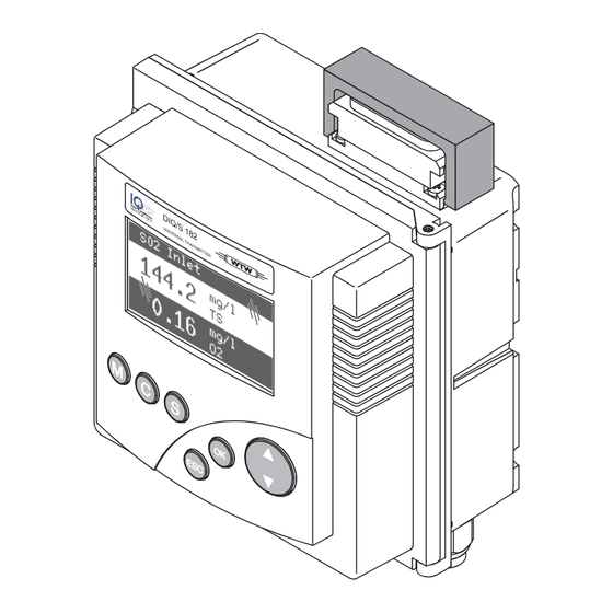
Operation Operating elements Display Toggle switch Key pad Fig. 4-1 Operating elements of the DIQ/S 182-PR Functions Function Switches directly to the measured value display from all operating situations Starts calibration of the sensor selected in the measured value display... -
Page 62: Measured Value And Status Display
Operation System 182 Measured value and status display With the key you switch to the last selected measured value and status display from any operating situation. Entries that are not completed are ignored while doing so. By pressing once again you cyclically switch between further display options. - Page 63 System 182 Operation Select the PROPERTIES menu with . With this menu you can put sensors in the maintenance condition and prompt important data (calibration data, error messages, operating states, software versions, etc.). Open the SETTINGS menu with Special The following displays inform you of special states of sensors sensor conditions...
-
Page 64: Working With The Settings Menu
Operation System 182 Working with the SETTINGS menu Note All settings in the SETTINGS menu can be protected by a password against unauthorized changing. For more detailed information on password protection, see section 4.6. 4.3.1 Selection menus Pressing switches from the measured value display to the SETTINGS menu (main menu). -
Page 65: Setting Tables
System 182 Operation 4.3.2 Setting tables In the setting tables, you make the actual settings. Two lines together represent each setting. The name of the setting is in the upper line on the left side of the display. The corresponding value is in the line below on the right side. -
Page 66: Entry Mode
Operation System 182 4.3.3 Entry mode In the entry mode, you can change individual values or enter a character string. Depending on the value type, change a value as follows Fixed values of a selection list (e.g. sensor measuring ranges): This is the most frequent form of an entry. - Page 67 System 182 Operation If you want to correct a previously selected character while entering, select the thin arrow to the left b and press . This moves the entry mark by one digit to the left. Thus you can go back to the required character.
-
Page 68: Properties Menu
Operation System 182 PROPERTIES menu 4.4.1 Overview Pressing switches from the measured value display to the PROPERTIES menu. In the PROPERTIES menu, you can prompt calibration data and various information on system components. Moreover, you can switch on and off the maintenance condition of a sensor. Fig. -
Page 69: Maintenance Condition
System 182 Operation 4.4.2 Maintenance condition When an IQ sensor is calibrated, cleaned, serviced or repaired, the maintenance condition for the relevant IQ sensor should always be switched on. In the maintenance condition apart from the measured value display, the system does not react to the current measured value or the condition of the selected IQ sensor ... - Page 70 Operation System 182 Recommended Switch on the maintenance condition for the IQ sensor. The proceeding for cleaning, measured value display flashes. maintenance and repair Pull the sensor out of the sample. Carry out the cleaning, maintenance or repair (removal and replacement) of the sensor.
-
Page 71: Sensor Status Sxx
System 182 Operation 4.4.3 Sensor status Sxx In the SENSOR STATUS Sxx menu you can prompt the following information on a sensor: Type and series number Software status Error and info messages ("log book") Data of the last calibration (only for sensors that can be calibrated) Fig. - Page 72 Operation System 182 Calibration data You can view the data of the last calibration under the Cal menu item. Sensors that have not yet been calibrated do not have this menu item. The symbol in the Cal line quotes the validity state: = valid = invalid The content and form of the calibration data depend on the sensor type.
- Page 73 System 182 Operation Type number Structure of the message code Type Category Fig. 4-10 Message code Pos. Information Explanation Info message (I) Category Error message (E) Calibration (C) Type Installation and commissioning (I) Instructions for service and repair (S) ...
- Page 74 Operation System 182 Select the Log... menu item and press The log book is displayed. Highlight the message to be acknowledged and press . The detailed message text is displayed. Scroll through the text with the toggle switch Press . Thus you acknowledge the message (). Press once again.
-
Page 75: Calibration Of Sensors
System 182 Operation Calibration of sensors Note Sensors can be protected by a password against unauthorized calibration. For more detailed information on password protection, see section 4.6. General proceeding Switch to the measured value display with Select the sensor to be calibrated with (in the single display, the sensor being displayed is always selected at the same time). - Page 76 Operation System 182 Confirm the calibration data with . Calibration is completed with this. The following display message describes the further steps to put the sensor into operation again. Putting the sensor into Confirm with . The display returns to the measured value operation after display (the measured value flashes as the sensor is still in the calibrating...
-
Page 77: Passwords
System 182 Operation Passwords You can assign and activate two passwords for the System 182. Settings password protects all settings in the SETTINGS menu. If the password is active, all settings can be viewed but not changed. The password query appears on leaving a setting table with the Save and quit command. - Page 78 Operation System 182 4 - 18 ba75503e07 04/2012...
-
Page 79: The Settings Menu
MIQ/IF232. More detailed information is given in the operating manual of the IQ Softwarepack, which can be downloaded under www.WTW.com. Language In this menu, you can set the system language. - Page 80 English. To activate the selected system language for this component, a software update of the component is required. Contact WTW. Sensor S01/S02 In this menu, you can assign a name of your choice to a sensor and adjust the sensor so it optimally meets the requirements of your application (measured parameter, measuring range, etc.).
- Page 81 System 182 The SETTINGS menu Edit the setting table as described in section 4.3.2. Note To accept all settings, you have to highlight the Save and quit menu item at the lower end of the setting table and press . If you exit the setting table via /Beenden or the Beenden menu item, all changes are ignored.
-
Page 82: Relay Output R1/R2/R3
ELAY OUTPUTS PROFIBUS config. You can set the PROFIBUS address in this menu (proceeding, see section 7.3). All information needed to connect the DIQ/S 182-PR to a PROFIBUS plant is given in chapter 7 PROFIBUS CONNECTION System The settings in the SYSTEM menu comprise: ... - Page 83 System 182 The SETTINGS menu Delivery condition Settings Default values Language English Pressure/Altitude 1013 mbar / 0 m Settings password 1000 / inactive Calibration password 1000 / inactive Sensor settings Sensor dependent (see settings tables in the respective sensor operating manual). Note: Calibration of the sensor is stored in the sensor and is retained when the system...
- Page 84 The SETTINGS menu System 182 5 - 6 ba75503e07 04/2012...
-
Page 85: Relay Outputs
System 182 Relay outputs Relay outputs General information The DIQ/S 182-PR Universal Transmitter has three relay outputs and one PROFIBUS output. System monitoring Functions for relay outputs Sensor monitoring Limit indicator Frequency output Pulse-width output ... -
Page 86: Linking And Adjusting: General Proceedings
Relay outputs System 182 Linking and adjusting: general proceedings 6.2.1 Linking relay outputs Linking options You have the following options of linking relay outputs: Sensor S01 The output is linked with sensor 01 Sensor S01 The output is linked with sensor 02 ... -
Page 87: Deleting A Link With An Output
System 182 Relay outputs 6.2.2 Deleting a link with an output If you no longer need a link you can erase the link. Proceeding: erasing a Open the SETTINGS menu with link Using , select and confirm the Relay output Rx menu item (corresponding to sensor 1, 2 or 3). -
Page 88: Setting Outputs
Relay outputs System 182 6.2.3 Setting outputs Proceeding: setting an Open the SETTINGS menu with output Using , select and confirm the Relay output Rx menu item (corresponding to sensor 1, 2 or 3). Confirm the selection Set output with The setting table of the output is displayed. -
Page 89: Basic Information On Relay Functions
System 182 Relay outputs Basic information on relay functions In this chapter, you will find general basic information concerning the following relay functions: Event monitoring (see section 6.3.1) Limit indicator (see section 6.3.2) Proportional output (see section 6.3.3) 6.3.1 Event monitoring When using a relay for event monitoring, a relay action (Open, Close) occurs when the monitored event takes place. - Page 90 Relay outputs System 182 Monitoring limiting Measured values using one or two value relays Relay 1 Hysteresis UL Hysteresis LL Relay 2 Time Fig. 6-1 Switching points for relays with the function of a limit indicator Upper limit value (relay 1) exceeded Selected switching delay t1 for relay 1 expired Relay 1 switches Hysteresis for upper limiting value (relay 1) undercut...
-
Page 91: Proportional Output
System 182 Relay outputs 6.3.3 Proportional output In the case of proportional output, a relay switches cyclically on and off in a defined measured value range (proportional range). At the same time, the relay switches with a: duration of operation that corresponds to the measured value (pulse-width output, see page 6-9) or ... - Page 92 Relay outputs System 182 Switching frequency f or Output with one relay Pulse width Proportional band Measured value Fig. 6-2 Output with one relay Output with two relays Switching frequency f or Pulse width Proportional bands Relay 1 and 2 Measured value Relay 1 Relay 2...
- Page 93 System 182 Relay outputs Pulse width output The output via the pulse width is used, e.g. for controlling valves. Pulse-width regulation changes the duration of operation (ton) of the output signal. Depending on the position of the measured value in the proportional range, the relay is operated for a longer or shorter period.
- Page 94 Relay outputs System 182 Frequency output Switching frequency output is used, e.g. for controlling dosing pumps. In contrast to the pulse-width output, not the pulse width is modulated with frequency output but the switching frequency of the output signal. Depending on the position of the measured value in the proportional range, the relay is switched more often or less often.
- Page 95 System 182 Relay outputs Characteristic curves Through the selection of the Start value and End value, the proportional output can be operated with a positive or negative characteristic curve. Positive characteristic curve: Select the End value to be greater than the Start value. The turn-on duration or frequency increases with an increasing measured value (see page 6-12).
- Page 96 Relay outputs System 182 Positive characteristic The proportional output range begins above the initial value. If the curve proportional range is undercut or exceeded, the selected behavior comes into force. Pulse width v [%] Cycle duration T Of f Proportional band Time Measured value 2...
- Page 97 System 182 Relay outputs Negative characteristic The proportional output range begins below the initial value. If the curve proportional range is undercut or exceeded, the selected behavior comes into force. Pulse width v [%] Cycle duration T Of f Proportional band Time Measured value 1...
-
Page 98: Setting Table For Relays
Relay outputs System 182 Setting table for relays 6.4.1 Functions and settings To set a relay its function has to be selected first. Then the relevant setting table is displayed: Relay function and Function Setting table relevant setting tables No function The relay output is not used. -
Page 99: System Monitoring
Settings Selection Explanations Power failure The Power failure On function monitors the supply voltage in DIQ/S 182-PR. If the voltage falls below a critical value, the relay switches. Collective error The Collective error function simultaneously monitors the proper function of all sensors. -
Page 100: Sensor Monitoring
Relay outputs System 182 6.4.3 Sensor monitoring Function The Sensor monitoring function enables to monitor sensor errors and the maintenance condition. In order to set up the Sensor monitoring function for a relay output, the relay output must be linked with a sensor (see section 6.2.1). Settings Setting Selection... -
Page 101: Limit Indicator
System 182 Relay outputs 6.4.4 Limit indicator Function The characteristic of the limit indicator is laid down in the Limit value UL, Limit value LL, Hysteresis UL and Hysteresis LL settings. The fundamentals of the function are described in the introductory chapter (see section 6.3.2). -
Page 102: Frequency Output
Relay outputs System 182 6.4.5 Frequency output Function The characteristic of the frequency output is laid down in the Start value, End value, Frequency (f) min. and Frequency (f) max. settings. The fundamentals of the function are described in the introductory chapter (see section 6.3.3). -
Page 103: Pulse-Width Output
System 182 Relay outputs 6.4.6 Pulse-width output Function The characteristic of the pulse width output is laid down in the Start value, End value, Pulse width (v) min. and Pulse width (v) max. settings. The fundamentals of the function are described in the introductory chapter (see section 6.3.3). -
Page 104: Sensor-Controlled Cleaning
Relay outputs System 182 6.4.7 Sensor-controlled cleaning With the Sensor controlled function, the relay is controlled by a linked sensor. Controller version from 2.80 Requirements Sensor that transmits signals to trigger a cleaning cycle, e.g. UV/VIS sensor Settings Setting Selection/Values Explanation... - Page 105 System 182 Relay outputs 6.4.8 Cleaning Function The Cleaning function enables the time controlled automatic start of the sensor cleaning function with the aid of a relay of the Universal Transmitter. The relay controls the DIQ/CHV valve module and switches on or off the compressed air for the CH sensor cleaning head. In order to set up the Cleaning function for a relay output, the relay output must be linked with a sensor (see section 6.2.1).
-
Page 106: Cleaning
Relay outputs System 182 Settings Setting Selection/Values Explanation Reference time (h) 0 ... 23 h Time at which a cleaning cycle is Reference time 0 ... 60 min started. Further (min) cleaning cycles will be performed at the times specified by the cleaning interval. - Page 107 System 182 Relay outputs Example Setting Result Reference time (h): Reference time: 12:00 hours Reference time This specifies the following (min): Hours (h) start times: Interval unit: 04:00, 12:00 and 20:00 hours Cleaning interval: t1a t1b relay condition closed open Time 00:00 04:00...
-
Page 108: Manual Control
Relay outputs System 182 Canceling the cleaning A running cleaning cycle is canceled: Automatically – If the sensor switches to the inactive condition during the cleaning cycle Manually – By pressing – By switching on the maintenance condition Each time the cleaning cycle is canceled, the relay opens immediately. -
Page 109: Behavior Of Linked Relay Outputs
System 182 Relay outputs Behavior of linked relay outputs 6.5.1 Behavior in case of error For linked relay outputs, you can specify the behavior in case of errors. Depending on the use of the output, the behavior in case of errors is set in the following menus: Output menu... - Page 110 Relay outputs System 182 6 - 26 ba75503e07 04/2012...
-
Page 111: Profibus Connection
After changing the bus address, have the devices been restarted (switched off and on again)? Note: The DIQ/S 182-PR does not have to be restarted. Do the addresses projected in the master correspond to the actual addresses? Are all addresses less than or equal to the parameter... -
Page 112: Connecting The Profibus Cable
Connecting the PROFIBUS cable The PROFIBUS cable is connected to the DIQ/S 182-PR using a 9-pin D-SUB connector on the top of the housing. As connector on the cable side, we exclusively recommend one of the following two connectors. - Page 113 Use connectors recommended by WTW only. When the connector is removed, the connection socket of the DIQ/S 182-PR must be closed with the blind plug and secured with the safety bracket. Note Use PROFIBUS cables according to EN 50170, cord type A.
- Page 114 PROFIBUS connection System 182 approx. 100 mm Fig. 7-2 DIQ/S 182-PR with Phoenix connector Pin assignment of the Color* Name Function connector B line Positive RxD/TxD according to RS 485 specification Request To Send GND BUS Reference potential for data lines and...
-
Page 115: Setting The Profibus Address
Profibus master. The GSD file for the IQ S is found on the CD-ROM provided ENSOR (file name: IQMC06D1.GSD). The current GSD file is also provided on the Internet under www.WTW.com. ba75503e07 04/2012 7 - 5... -
Page 116: Transmitted Sensor Data
The data is transmitted in two steps: The Profibus master transmits the request to the DIQ/S 182-PR to supply data for the sensor with a certain sensor number. The DIQ/S 182-PR checks whether the requested sensor number is present and returns the data for the sensor with the respective sensor number to the PROFIBUS master. -
Page 117: Sensor Administration Under Profibus
Measured value status (main and secondary measured value) Main measured value Secondary measured value Note The transmitted data of all IQ S sensors is given in the WTW ENSOR document, "IQ S sensors: coded data for field bus ENSOR communication"... - Page 118 PROFIBUS connection System 182 Creating the assignment You want to install an IQ S system and, at the same time, ENSOR of sensor numbers create a specific sequence of sensor number assignments to the sensors. Carry out a system start without any sensors (see section 3.10).
-
Page 119: Output Data
System 182 PROFIBUS connection 7.5.3 Output data (1 byte - from the PROFIBUS master to the DIQ/S 182-PR) Address Information Offset 0h Sensor number (Sxx) in the IQ S (Int8) Bit 7-0 ENSOR 7.5.4 Input data (16 bytes - from the IQ S... -
Page 120: Data Formats
PROFIBUS connection System 182 7.5.5 Data formats Measured values The data for the main and secondary measured values are transmitted in the IEE-754 standard 32-bit floating point format. Address Bit representation MSB* LSB* Offset 0h bits 31-24 S = sign (bit 31) S E E E E E E E E = exponent Offset 1h bits 23-16... -
Page 121: Profibus Error Diagnosis
– Incorrect protocol – Check the version of the GSD file – Adapt the protocol – DIQ/S 182-PR defective – Send DIQ/S 182-PR to WTW The PLC does not Cause Remedy receive any plausible – Input data and output data –... - Page 122 PROFIBUS connection System 182 7 - 12 ba75503e07 04/2012...
-
Page 123: Maintenance And Cleaning
Component Maintenance IQ sensors Depending on the type of sensor (see the component operating manual of the sensor) DIQ/S 182-PR, No maintenance required DIQ modules, MIQ modules Cleaning DIQ/S 182-PR, Clean components mounted in the open of gross contamination as DIQ modules, necessary. - Page 124 Maintenance and cleaning System 182 8 - 2 ba75503e07 04/2012...
-
Page 125: What To Do If
What to do if ... Information on errors Log book The DIQ/S 182-PR system performs a comprehensive cyclical self test during operation. While doing so, the system identifies all states that deviate from normal operation and enters corresponding messages in the log book (information or error message). -
Page 126: Replacing System Components
DIQ/CHV Cables (SNCIQ, SACIQ). Warning If the DIQ/S 182-PR Universal Transmitter is opened and the MIQ/ PS power supply module is operating, there is a danger to life due to possible hazard of electric shock from line voltage. Before... -
Page 127: Adding And Replacing Iq Sensors
If no suitable inactive dataset is available, a newly connected IQ sensor is recognized and added automatically. Note The DIQ/S 182-PR Universal Transmitter can display and administrate up to two main measured parameters. If necessary, an inactive dataset has to be erased to be able to add a new sensor. - Page 128 What to do if ... System 182 Case 2: The type of sensor is identical Operator intervention is required with the type of sensor in an here. The connected IQ sensor inactive dataset (or several can: inactive datasets), but the serial –...
- Page 129 System 182 What to do if ... Operating sequence in Connect the IQ sensor. case 2 Change to the measured value display with . The component database is updated. The following display appears (example): Select the required option with and confirm with –...
- Page 130 What to do if ... System 182 9 - 6 ba75503e07 04/2012...
-
Page 131: Technical Data
10.1 DIQ/S 182-PR Dimensions Lateral view: Front view: 144.0 43.0 52.2 23.0 11.0 Rear view: 115.0 16.5 70.0 Stack mounting: 137.0 Fig. 10-1 Dimension drawing of the DIQ/S 182-PR (dimensions in mm) Test marks cETLus, CE ba75503e07 04/2012 10 - 1... - Page 132 Weight Approx. 0.7 kg Type of protection – IP 66 – corresponds to NEMA 4X The DIQ/S 182-PR Universal Transmitter is not suitable for Conduit Connection Ambient conditions Temperature Operation - 20 °C ... + 55 °C (-4 ... 131 °F) Storage - 25 °C ...
- Page 133 Fuse rating on the operator side: max. 2 A requirements Relay functions Programmable as: – Opener or closer – Limit monitor – Monitoring of the warning and error signals of the DIQ/S 182-PR – Proportional frequency output – Proportional pulse width output ba75503e07 04/2012 10 - 3...
- Page 134 System lightning Extended protective characteristics as protection opposed to EN 61326 FCC, class A Note Any combination of the DIQ/S 182-PR with IQ S products in ENSOR a user-specific system achieves the listed EMC characteristics. Instrument safety Applicable norms – EN 61010-1 –...
-
Page 135: Miq Modules
System 182 Technical data 10.2 MIQ modules Note Technical data on special MIQ modules are given in the respective operating manuals. Dimensions 144.0 52.2 Front view: Side view: 115.0 11.0 70.0 16.5 Rear view Stack mounting: Fig. 10-2 Dimension drawing of MIQ module (dimensions in mm) ba75503e07 04/2012 10 - 5... - Page 136 Technical data System 182 Mechanical Maximum number of 2 plus Universal Transmitter DIQ/S 182-PR construction MIQ modules in a module stack Enclosure material Polycarbonate with 20 % glass fiber Weight Approx. 0.5 kg (type-dependent) Type of protection – IP 66 –...
-
Page 137: Diq/Jb
System 182 Technical data 10.3 DIQ/JB Dimensions DIQ/JB Fig. 10-3 Dimension drawing of DIQ/JB (dimensions in mm) Mechanical Enclosure material Polystyrene construction Weight Approx. 0.2 kg Type of protection IP 66 Electrical connections (7 passive, potential free terminals for line extension or branching) Terminals Terminal type Screw-type terminal strip... -
Page 138: Diq/Chv
Technical data System 182 10.4 DIQ/CHV Dimensions DIQ/CHV Fig. 10-4 Dimension drawing of DIQ/CHV (dimensions in mm) Mechanical Enclosure material Polystyrene construction Weight Approx. 0.3 kg Type of protection IP 66 1 x valve switching contact Electrical connections 4 x potential-free terminals to connect interface lines Terminal strip inside the enclosure: (HILFLSKONTAKTE) VENTIL... - Page 139 Approx. 22 V Max. switching current Approx. 40 mA Caution The valve may only be operated with the auxiliary voltage of the DIQ/S 182-PR Universal Transmitter. Compressed air Required air quality Dry, free of dust and oil Operating pressure Max. 7x10...
-
Page 140: Space Required By Mounted Components
Technical data System 182 10.5 Space required by mounted components Wall mounting and top hat rail mounting Wall mounting top hat rail mounting Space required for screwdriver Fig. 10-5 Space required for wall and top hat rail mounting: (dimensions in mm) Panel mounting Panel mounting Space required... -
Page 141: Accessories And Options
Set for mounting of the DIQ/S 182-PR or an THS/IQ 480 050 MIQ module on a 35 mm top hat rail according to EN 50022 Note Other accessories for the System 182 are given in the WTW catalog or on the Internet. ba75503e07 04/2012 11 - 1... - Page 142 Accessories and options System 182 11 - 2 ba75503e07 04/2012...
-
Page 143: Index
System 182 Index Index Air pressure ..........5-4 GSD file ............ 7-5 Altitude ............5-4 Ambient conditions ........10-2 Authorized use .......... 2-2 Inactive dataset ........5-3, 9-3 Auxiliary voltage Info symbol ........4-3, 4-11 Terminal strip ........3-46 Usage ..........3-40 Key functions .......... - Page 144 Index System 182 Stack expansion backwards ...........3-9 Obligations of the operator ......2-3 forwards ..........3-6 Operating elements ........4-1 Start checklist ..........3-42 Operational safety ........2-2 Starting the system ........3-42 Status sensor ..........4-11 Password System ..........4-8 Calibration .........4-17 System language ........5-1 Settings ..........4-17 System monitoring (relay) .......6-15 Power failure ..........1-3 System status ..........4-8...
-
Page 145: Appendix (Store Separately If Required)
System 182 Appendix (store separately if required) Appendix (store separately if required) 13.1 Forgotten the password? Proceeding: Open the SETTINGS menu with prompting the password Depending on the password to be prompted, use to select and confirm the menu item, Settings Calibrate . - Page 146 Appendix (store separately if required) System 182 13 - 2 ba75503e07 04/2012...
Need help?
Do you have a question about the DIQ/S 182-PR and is the answer not in the manual?
Questions and answers