Sign In
Upload
Manuals
Brands
wtw Manuals
Controller
DIQ/S 182-PR
wtw DIQ/S 182-PR Manuals
Manuals and User Guides for wtw DIQ/S 182-PR. We have
2
wtw DIQ/S 182-PR manuals available for free PDF download: Operating Manual, System Operating Manual
wtw DIQ/S 182-PR Operating Manual (216 pages)
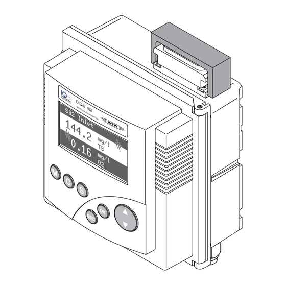
MEASURING SYSTEM FOR 2 DIGITAL SENSORS, WITH 4 CURRENT OUTPUTS
Brand:
wtw
| Category:
Measuring Instruments
| Size: 2 MB
Table of Contents
System 182 -
9
Table of Contents
9
1 Overview
13
Structure and Function
13
Behavior of the System in the Case of Power Failure
15
2 Safety
17
Safety Information
17
Safety Information in the Operating Manual
17
Safety Signs on the Product
17
Further Documents Providing Safety Information
17
Safe Operation
18
Authorized Use
18
Requirements for Safe Operation
18
Unauthorized Use
18
User Qualification
18
3 Installation
21
Scope of Delivery
21
Basics of the Installation
21
Requirements of the Measurement Location
21
Additional MIQ Power Supply Modules
21
Safety Requirements on the Electrical Installation
23
Installation Guidelines for Lightning Protection
23
Connecting System Components
26
Connecting MIQ Modules: General Information
26
Variant 1: Stack Expansion Forwards
28
Variant 2: Stack Expansion Backwards
31
Distributed Mounting
34
Connecting IQ Sensors
38
On Site Mounting of the Universal Transmitter and MIQ Modules
40
General Information
40
Mounting on a Mounting Stand with the SSH/IQ Sun Shield
41
Mounting under the SD/K 170 Sun Shield
44
Panel Mounting
45
Top hat Rail Mounting
47
Using DIQ Modules (Accessories)
48
Diq/Jb
48
Diq/Chv
48
Installation of the DIQ Modules
49
Electrical Connections: General Instructions
50
Connecting the Voltage Supply
52
DIQ/S 182 (Line Power Version)
52
DIQ/S 182/24V (24 V Version)
56
Connections to the Relay and Current Outputs
59
General Installation Instructions
59
Usage of the Auxiliary Voltage
61
Commissioning
63
Installation Examples
64
Connecting Two Sensors Without Compressed Air Cleaning
64
Connecting Two Sensors with Compressed Air Cleaning
66
Connection of a Sensor that Is Located at a Distance
68
(Without Compressed Air Cleaning)
68
Figures of the Terminal Strips
69
4 Operation
71
Operating Elements
71
Measured Value and Status Display
72
Working with the SETTINGS Menu
74
Selection Menus
74
Setting Tables
75
Entry Mode
76
PROPERTIES Menu
78
Overview
78
Maintenance Condition
79
Sensor Status Sxx
81
Calibration of Sensors
85
Passwords
87
5 The SETTINGS Menu
89
Overview of the SETTINGS Menu
89
Language
89
Sensor S01/S02
90
System
91
Relay Output R1/R2/R3, Ma Output C1/C2
91
6 Outputs
93
Outputs of the DIQ/S 182
93
Linking and Adjusting: General Proceedings
94
Linking Outputs
94
Deleting a Link with an Output
95
Setting Outputs
96
Basic Information on Relay Functions
97
Monitoring
97
Limit Indicator
97
Proportional Output
99
Setting Table for Relays
106
Functions and Settings
106
System Monitoring
107
Sensor Monitoring
108
Limit Indicator
109
Frequency Controller
110
Pulse-Width Output
111
Sensor Controlled
112
Cleaning
114
Manual Control
116
Setting Tables for Current Outputs
117
Functions and Settings
117
Recorder
117
PID Controller
120
Fixed Current Value
124
Behavior of Linked Outputs
125
Behavior in Case of Error
125
Behavior in Non-Operative Condition
125
7 Maintenance and Cleaning
127
Maintenance
127
Cleaning
127
8 What to Do if
129
Information on Errors
129
Error Causes and Remedies
129
Replacing System Components
130
Replacing Passive Components
130
Adding and Replacing IQ Sensors
130
9 Technical Data
133
Diq/S 182
133
MIQ Modules
138
Diq/Jb
140
Diq/Chv
141
Space Required by Mounted Components
143
10 Accessories and Options
145
11 Index
147
12 Appendix (Store Separately if Required)
149
Forgotten the Password
149
Default Passwords
149
Miq/Cr3; Diq/Cr3 - List of
155
1 Overview
157
How to Use this Component Operating Manual
157
Iq Sensor Net
157
Features of the Combi Output Module
158
2 Safety Instructions
159
Authorized Use
160
General Safety Instructions
160
3 Installation
161
Scope of Delivery
161
Safety Requirements on the Electrical Installation
161
Installation in the IQ SENSOR NET
161
Electrical Connections: General Instructions
163
Connections to the Relay and Current Outputs
164
4 Settings
167
Basic Information on Relay Functions
168
Monitoring
168
Limit Indicator
169
Proportional Output
171
Entering / Editing the Name of an Output
178
Linking the Output with a Sensor
179
Deleting a Link with an Output
180
Setting the Relay Outputs
181
Relay Action
182
System Monitoring
183
Sensor Monitoring
184
Limit Indicator
185
Frequency Controller
187
Pulse-Width Contr
188
Cleaning
190
Sensor-Controlled
193
Manual Control
194
Alarm Contact
194
Setting of Current Outputs
195
Recorder
196
PID Controller
198
Fixed Current Value
203
Checking the Status of the Outputs
204
Behavior of Linked Outputs
205
Behavior in Case of Error
205
Behavior in Non-Operative Condition
206
Maintenance Condition of Sensors
207
Switching on the Maintenance Condition
208
Switching off the Maintenance Condition
208
5 Maintenance and Cleaning
209
Maintenance
209
Cleaning
209
6 Technical Data
211
7 Indexes
213
Explanation of the Messages
213
Error Messages
213
Info Messages
213
Advertisement
wtw DIQ/S 182-PR System Operating Manual (146 pages)
Modular measuring system for 2 digital sensors with PROFIBUS-DP output
Brand:
wtw
| Category:
Measuring Instruments
| Size: 2 MB
Table of Contents
Table of Contents
3
1 Overview
7
Structure and Function
7
Behavior of the System in the Case of Power Failure
9
2 Safety Instructions
11
User Qualification
11
Authorized Use
12
General Safety Instructions
12
3 Installation
15
Scope of Delivery
15
Requirements of the Measurement Location
15
Installation Guidelines for Lightning Protection
15
Connecting System Components
18
Connecting MIQ Modules: General Information
18
Variant 1: Stack Expansion Forwards
20
Variant 2: Stack Expansion Backwards
23
Distributed Mounting
26
Connecting IQ Sensors
30
On Site Mounting of the Universal Transmitter and MIQ Modules
32
General Information
32
Mounting on a Mounting Stand with the SSH/IQ Sun Shield
33
Panel Mounting
36
Top hat Rail Mounting
38
Using DIQ Modules (Accessories)
39
Diq/Jb
39
Diq/Chv
39
Installation of the Modules
40
Electrical Connections: General Instructions
41
Connecting the Voltage Supply
43
DIQ/S 182-PR (Line Power Version)
43
DIQ/S 182-PR/24V (24 V Version)
47
Additional MIQ Power Supply Modules
50
Connections to the Relay Outputs
52
General Installation Instructions
52
Usage of the Auxiliary Voltage
54
Commissioning
56
Installation Examples
57
Connecting Two Sensors Without Compressed Air Cleaning
57
Connecting Two Sensors with Compressed Air Cleaning
58
Figures of the Terminal Strips
60
4 Operation
61
Operating Elements
61
Measured Value and Status Display
62
Working with the SETTINGS Menu
64
Selection Menus
64
Setting Tables
65
Entry Mode
66
PROPERTIES Menu
68
Overview
68
Maintenance Condition
69
Sensor Status Sxx
71
Calibration of Sensors
75
Passwords
77
5 The SETTINGS Menu
79
Overview of the SETTINGS Menu
79
Language
79
Relay Output R1/R2/R3
82
PROFIBUS Config
82
System
82
6 Relay Outputs
85
General Information
85
Linking and Adjusting: General Proceedings
86
Linking Relay Outputs
86
Deleting a Link with an Output
87
Setting Outputs
88
Basic Information on Relay Functions
89
Event Monitoring
89
Limit Indicator
89
Proportional Output
91
Setting Table for Relays
98
Functions and Settings
98
System Monitoring
99
Sensor Monitoring
100
Limit Indicator
101
Frequency Output
102
Pulse-Width Output
103
Sensor-Controlled Cleaning
104
Cleaning
106
Manual Control
108
Behavior of Linked Relay Outputs
109
Behavior in Case of Error
109
Behavior in Non-Operative Condition
109
7 PROFIBUS Connection
111
PROFIBUS Checklist
111
Connecting the PROFIBUS Cable
112
Setting the PROFIBUS Address
115
GSD File
115
Transmitted Sensor Data
116
Overview
116
Sensor Administration under PROFIBUS
117
Output Data
119
Input Data
119
Data Formats
120
PROFIBUS Error Diagnosis
121
PROFIBUS Error Elimination
121
8 Maintenance and Cleaning
123
Maintenance
123
Cleaning
123
9 What to Do if
125
Information on Errors
125
Error Causes and Remedies
125
Replacing System Components
126
Replacing Passive Components
126
Adding and Replacing IQ Sensors
127
10 Technical Data
131
Diq/S 182-Pr
131
MIQ Modules
135
Diq/Jb
137
Diq/Chv
138
Space Required by Mounted Components
140
11 Accessories and Options
141
12 Index
143
13 Appendix (Store Separately if Required)
145
Forgotten the Password
145
Default Passwords
145
Advertisement
Related Products
wtw DIQ/S 182-XT-4-MOD
wtw System 182
wtw DIQ/S 182-XT-4
wtw DIQ/S 182-MOD
wtw Cond 1970i
wtw MULTILINE 1000
wtw pH 171 2K-RS
wtw Multi 197i
wtw 106 395
wtw ADA/TA 197 pH
wtw Categories
Measuring Instruments
Accessories
Laboratory Equipment
Control Unit
Touch terminals
More wtw Manuals
Login
Sign In
OR
Sign in with Facebook
Sign in with Google
Upload manual
Upload from disk
Upload from URL