Table of Contents
Advertisement
Quick Links
Advertisement
Table of Contents
Troubleshooting

Related Manuals for CTC Union EcoZenith i360 Series


Summary of Contents for CTC Union EcoZenith i360 Series
- Page 1 162 505 77-1 2020-09-15 Providing sustainable energy solutions worldwide Installation and Maintenance Manual CTC EcoZenith i360 Indoor model with heat pump control 3x400V / 1x230V / 3x230V Important! • Read carefully before use, keep for future reference. • Translation of the original instructions.
-
Page 2: Important! Information On Air Bleeding
Important! Information on air bleeding For the product to work as intended, the system must be fully bled. It is extremely important that a basic bleeding of the product is carried out systematically and carefully. Bleeding devices must be fitted to the system’s natural high points. A basic bleeding of the hot water tank can be carried out upon installation by releasing the safety valve, which must be fitted to the top of the product. - Page 3 162 505 77-1 2020-09-15 Installation and Maintenance Manual CTC EcoZenith i360...
-
Page 4: Table Of Contents
Table of Contents Important! Information on air bleeding 6.16 Sensor connection ______________________ ___________________________________________ Safety instructions 6.17 Current sensor connection _______________________________________________________ ________________________________ Technical data 6.18 Setting electrical output in backup power supply _______________________________________________________ Measurements 6.19 Resistance table for sensor _______________________________________________________ _______________________________ Overview CTC EcoZenith i360 Installation Communication _____________________________... -
Page 5: Safety Instructions
Safety instructions Turn off the power with an omnipolar switch before doing any work on the product. The product must be connected to protective earth. The product is classified as IPX1. The product must not be rinsed with water. When handling the product with a hoist ring or similar device, make sure that the lifting equipment, eyebolts and other parts are not damaged. -
Page 6: Technical Data
Technical data Designation CTC EcoZenith CTC EcoZenith CTC EcoZenith CTC EcoZenith i360 L i360 H i360 L 1x230V i360 L 3x230V General data Article number 589400001 589401001 589400002 589400003 7333077094485 7333077094478 7333077094492 7333077094508 Gross weight Net weight Dimensions DxWxH (with 781x694x1825 770x694x2090 781x694x1825... -
Page 7: Measurements
Heating medium system Water volume (V) (PED) Max operating Mpa/ 0.3/3.0 0.3/3.0 0.3/3.0 0.3/3.0 pressure (PS) (PED) Max operating °C temperature (TS) (PED) °C Max adjustable operating temperature Product Kvs value Pressure differential See pressure See pressure See pressure See pressure diagram for product differential diagram differential diagram... -
Page 8: Overview Ctc Ecozenith I360
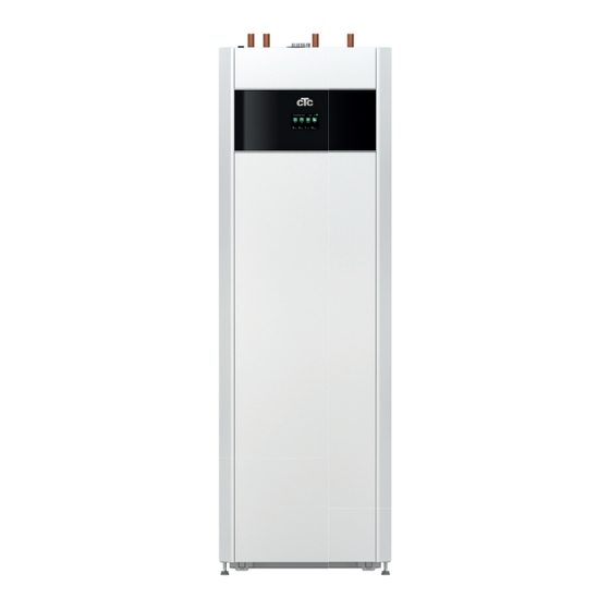
3. Overview CTC EcoZenith i360 The picture below shows the basic construction of CTC EcoZenith i360. If a heat pump is connected, the energy in the air or bedrock/ground is drawn up by the cooling system. The compressor then increases the temperature to a usable level. Afterwards it releases the energy for the heating circuit and DHW. -
Page 9: Compatible Heat Pumps
Compatible heat pumps CTC EcoAir 500M/600M CTC EcoAir 400 series CTC EcoPart 400 series CTC EcoPart 600 series series variable speed air-to- air-to-water fluid-to-water speed controlled liquid-to- water water • • CTC EcoAir 406 CTC EcoPart 406 • • CTC EcoAir 510M CTC EcoPart 612 •... -
Page 10: Delivery Includes
Delivery includes: • CTC EcoZenith i360. • Installation and Maintenance Manual. • Supplied Components (list and picture below of supplied components for CTC EcoZenith i360). Designation Quantity* Outdoor sensor 1/1/1/1 Room sensor 1/1/1/1 Safety valve 2.5 bar 3/4" ext. 1/1/1/1 Support sleeve 22x1 4/5/4/4 Filter ball valve with magnet... -
Page 11: Important To Remember
4. Important to remember! Check the following points at the time of delivery and installation: Transportation Transport the unit to the installation site before removing the packaging. Handle the product in the following manner: • Forklift. • Lifting eye that has been fitted to the lifting sleeve on top of the product in the expansion connection. -
Page 12: Pipe Installation
5. Pipe installation Minimum water volume in the heating The installation must be carried out in accordance with the applicable circuit (>25 ºC) for standards. Do not forget to flush the heating circuit clean before reliable defrosting connecting. Apply all the installation settings based on the description in the functionality: section entitled "First start". -
Page 13: Schematic Diagram For Air-To-Water Heat Pump
Schematic diagram for air-to-water heat pump CTC EcoZenith i360 1 heating circuit 1 compatible heat pump from the CTC EcoPart 400 or 600 series. CTC EcoZenith i360... -
Page 14: Full Schematic Diagram
Full schematic diagram This is a full schematic diagram of the connection options for the CTC EcoZenith i360. Different installations and systems may look different, e.g. a one or two-pipe system, In addition to basic which means that the finished installation may be different. installation Heating circuit 1 Heating circuit 2... -
Page 15: Interactive Schematic Diagram
Interactive schematic diagram On CTC’s website, you can bring up and print out the schematic diagram for the installation you want by clicking the option in the interactive pdf file. Solar Energy mixing valve diverting valve control valve solenoid valve non-return valve shut-off valve sensor... -
Page 16: Install Hot Water Pipe
Install hot water pipe 5.5.1 Install dirt fi lter (1). 5.5.2 Install cold water supply (2) with non-return valve. 5.5.3 Install the fi lling valve (3). 5.5.4 Install hot water pipe from tank (4). Check function – flush. 5.5.1 5.5.4 5.5.3 5.5.2 Plate heat exchanger... -
Page 17: Install Pipe For Radiator System
Install pipe for radiator system Heating circuit 5.6.1 Install primary fl ow with shut-off valve. 5.6.2 Install return line. 5.6.2 fi lling valve return from radiator system 5.6.1 primary fl ow to radiator system diverting valve DHW/HS electric fl ow heater circulation pump 5.6.3. - Page 18 5.6.3 Adjust the pre-assembled expansion tank to the right pre-pressure by using the valve to raise or lower the pressure. Adjustment of pre-pressure. The pre-pressure in the expansion tank is calculated according to the height (H) between the highest-positioned radiator and the expansion tank. The pre-pressure must be checked/set before the system is filled with water.
-
Page 19: Install Pipes To And From The Heat Pump
Install pipes to and from the heat pump Heat pump 5.7.1 Install pipe to the heat pump with solenoid fi lter ball valve. 5.7.2 Install pipes from heat pump. Install any adjustable by-pass coupling past the heat pump. (*a by-pass coupling is only used for electric operation without a heat pump). -
Page 20: Install Waste Water Piping
Install waste water piping Waste water 5.8.1 Fit the safety valve, bleed valve and manometer. Components and assembly instructions are included in the additional pack for the product. 5.8.2 Install waste water piping. 5.8.3 The bleed valve is activated by loosening the bleeder screw, which should then be closed after a few minutes. -
Page 21: Fill The Heating Circuit
Fill the heating circuit Fill the heating circuit 5.9.1 Open the filling valve and fill the heating system. 5.9.2 Turn the safety valve to release air more quickly during filling; close the filling valve when the system is full. 5.9.3 Check the manometer for a filled cold system (approx. -
Page 22: Bleed The Entire System
5.10 Bleed the entire system Bleed the system 5.10.1 Bleed the CTC EcoZenith i360 valve using the safety valve, make sure also that the screw for the automatic bleed valve has been activated. 5.10.2 Bleed, activate bleed valve for heat pump. 5.10.3 Bleed high points for the radiator system. -
Page 23: Electrical Installation
6. Electrical installation Safety information (x 2) The following safety instructions must be observed when handling, installing and using the product: Turn off the power with an omnipolar switch before doing any work on the product. • The product is classified as IPX1. The product must not be rinsed with water. -
Page 24: Overview Of Basic Electrical Installation
Overview of basic electrical installation Basic installation includes: EcoZenith i360 CTC EcoZenith i360 1 heating circuit 1 heating system 1 CTC EcoAir heat pump in the 400, 1 heat pump in the CTC EcoPart 500 or 600 series 400 or 600 series In such cases, work flow points 1–6 can be used for electrical installation. -
Page 25: List Of Functions
List of functions Function Relay card Sensor [B] Pump [G] Valve [Y] Other Basic installation (A2) (X2) B11, B15, (G5), (G11) COM HP – (B18), B103 HP A1* Return temp., installation without (A2) HP A1 Heating circuit 2 (A2) B2, B12 Ventilation (X2) Passive cooling... -
Page 26: Electrical Parts List
Electrical parts list Designation Spec Designation Spec Display Circulation pump for DHW circ. Relay/main card Charging pump Expansion card Circulation pump, pool Gateway heating Primary flow sensor 1 NTC 22K Contactor 1 Primary flow sensor 2 NTC 22K Flexible remote control/ Sensor, DHW tank NTC 22K SmartGrid... - Page 27 See picture terminal X2, previous page. B102 See chapter “Installation Communication”. See wiring diagram, next page. Accessories, see "Wiring diagram Extension Card". CTC EcoZenith i360...
-
Page 28: Wiring Diagram Ctc Ecozenith I360 3X400V Relay Card A2
Wiring diagram CTC EcoZenith i360 3x400V Relay card A2 GNYE GNYE GNYE /1.F4 /1.F4 /1.F4 -F1:2 -F1:2 -F1:2 /1.F4 /1.F4 /1.F4 -F10:B1 -F10:B1 -F10:B1 -F10 -F10 -F10 /2.A2 /2.A2 /2.A2 #252 #252 #252 -X3:N -X3:N -X3:N EL3B EL3B EL3B /2.D7 /2.D7 /2.D7 -X11:6... - Page 29 -X30 -X30 COM1 COM1 VOLTAGE- VOLTAGE- DETECTION DETECTION -X104:1 -X104:1 #261 #261 /3.A4 /3.A4 -X104:2 -X104:2 #262 #262 /3.A4 /3.A4 -X104:3 -X104:3 #263 #263 /3.A4 /3.A4 -W15 -W15 -G11 -G11 #112 #112 /3.C7 /3.C7 -X2:G47 -X2:G47 #113 #113 /3.C7 /3.C7 -X2:G48 -X2:G48 -X102...
-
Page 30: Wiring Diagram Ctc Ecozenith I360 3X400V Flow Heater E15
Wiring diagram CTC EcoZenith i360 3x400V Flow heater E15 CTC EcoZenith i360... -
Page 31: Wiring Diagram Ctc Ecozenith I360 3X400V Terminal Block X2
Wiring diagram CTC EcoZenith i360 3x400V Terminal Block X2 External 230V External 230V 913145401 913145401 /1.E4 /1.E4 -F1:1 -F1:1 -W12 -W12 /1.E6 /1.E6 -A2:A15 #111 -A2:A15 #111 External 230V External 230V /1.E5 /1.E5 -A2:A16 #110 -A2:A16 #110 /1.E4 /1.E4 -A2:A36 #109 -A2:A36 #109... -
Page 32: Wiring Diagram Ctc Ecozenith I360 1X230V Relay Card A2
Wiring diagram CTC EcoZenith i360 1x230V Relay card A2 GNYE -W15 -W15 /1.F4 -F1:2 -PE Heater -PE Heater /1.F4 -F10:B1 -F10 /2.A2 #252 -X3:N -W14 -W14 -F10 -F10 #248 #248 /1.F5 /1.F5 -A2:A23 -A2:A23 EL3B EL3B EL3B /2.D7 /2.D7 /2.D7 #355 #355 -X11:6... - Page 33 -X30 -X30 COM1 COM1 VOLTAGE- VOLTAGE- DETECTION DETECTION -X104:1 -X104:1 #350 #350 /3.A4 /3.A4 -X104:2 -X104:2 #351 #351 /3.A4 /3.A4 -X104:3 -X104:3 #352 #352 /3.A4 /3.A4 -W17 -W17 -G11 -G11 #112 #112 /3.C7 /3.C7 -X2:G47 -X2:G47 #113 #113 /3.C7 /3.C7 -X2:G48 -X2:G48 -X102...
-
Page 34: Wiring Diagram Ctc Ecozenith I360 1X230V Flow Heater E15
Wiring diagram CTC EcoZenith i360 1x230V Flow heater E15 CTC EcoZenith i360... -
Page 35: Wiring Diagram Ctc Ecozenith I360 1X230V Terminal Block X2
Wiring diagram CTC EcoZenith i360 1x230V Terminal Block X2 External 230V External 230V 913145401 913145401 /1.F4 /1.F4 -F1:1 #300 -F1:1 #300 -W12 -W12 /1.E6 /1.E6 -A2:A15 #111 -A2:A15 #111 External 230V External 230V /1.E5 /1.E5 -A2:A16 #110 -A2:A16 #110 /1.E4 /1.E4 -A2:A36 #109... -
Page 36: Wiring Diagram Ctc Ecozenith I360 3X230V Relay Card A2
6.10 Wiring diagram CTC EcoZenith i360 3x230V Relay card A2 GNYE /1.F4 -F1:2 /1.F4 -F10:B1 -PE Heater -PE Heater -F10 /2.A2 #252 -X3:N -F10 -F10 #248 #248 /1.F5 /1.F5 -A2:A23 -A2:A23 EL3B EL3B EL3B /2.D7 -X11:6 EL3A EL3A EL3A /2.C7 -X11:5 EL2B EL2B... - Page 37 -X30 -X30 COM1 COM1 VOLTAGE- VOLTAGE- DETECTION DETECTION -X104:1 -X104:1 #146 #146 /3.A4 /3.A4 -X104:2 -X104:2 #147 #147 /3.A4 /3.A4 -X104:3 -X104:3 #148 #148 /3.A4 /3.A4 -W17 -W17 -G11 -G11 #112 #112 /3.C7 /3.C7 +Ande2-X2:G47 +Ande2-X2:G47 #113 #113 /3.C7 /3.C7 +Ande2-X2:G48 +Ande2-X2:G48 -X102...
-
Page 38: Wiring Diagram Ctc Ecozenith I360 3X230V Flow Heater E15
6.11 Wiring diagram CTC EcoZenith i360 3x230V Flow heater E15 CTC EcoZenith i360... -
Page 39: Wiring Diagram Ctc Ecozenith I360 3X230V Terminal Block X2
6.12 Wiring diagram CTC EcoZenith i360 3x230V Terminal Block X2 External 230V External 230V 913145401 913145401 /1.F4 /1.F4 -F1:1 #300 -F1:1 #300 -W12 -W12 /1.E6 /1.E6 -A2:A15 #111 -A2:A15 #111 External 230V External 230V /1.E5 /1.E5 -A2:A16 #110 -A2:A16 #110 /1.E4 /1.E4 -A2:A36... -
Page 40: Connection Table For Electrical Components
6.13 Connection table for electrical components This table specifies the connections for components for the EcoZenith i360 relay card A2 or terminal board X2. (See also the wiring diagram). Connection Designation Option Card Terminal Wire block A1 – Display board Display COM A1 Patch... - Page 41 Connection Designation Option Card Terminal Wire block Heating circ. pump 1 Heating circ. pump 2 Brown Heating circ. pump 2 Yellow/green Heating circ. pump 2 Blue Circulation pump for hot water heat Brown exchanger Circulation pump for hot water heat Blue exchanger Circulation pump for hot water heat...
-
Page 42: Wiring Diagram For Expansion Card
6.14 Wiring diagram for Expansion card Accessories Pos. External Boiler 1) temp. sensor G67/G68 2) valve A27/A28/A29 CTC EcoZenith i360... -
Page 43: Connection Table For Expansion Card A3
6.15 Connection table for Expansion Card A3 This table shows the connections for components for CTC EcoZenith i360 Extension Card A3. (See also the wiring diagram for the extension card). Designation Terminal block/ Designation Terminal block/ cable cable Display COM2 Pump, bore hole X6:10 recharging... -
Page 44: Sensor Connection
6.16 Sensor connection The sensor is connected on top of terminal X2, behind the magnetic strip. See the wiring diagram and connection table for correct connection. Sensor terminal block 6.16.1 Connection of outdoor sensor (B15) The sensor should be set up on the house’s northwest or north side, so that Do not attach it is not exposed to morning and evening sun. - Page 45 6.16.3 Installation of sensor on pipe The sensing part is towards the end of the sensor (see sketch). • Attach the sensor using the cable tie provided. • Ensure that the sensor makes good contact with the pipe. Apply contact paste to the front part of the sensor between the sensor and the pipe if good contact is otherwise difficult to obtain.
-
Page 46: Current Sensor Connection
6.17 Current sensor connection A current sensor with three sensors is used for product models with 400V 3N~ 50Hz (3x400V) and 230V 3N~ 50Hz (3x230V) connections (see technical data). The three current sensors, one for each phase, are fitted on the fuse panel. Each phase from the electricity distribution board supplying the product is channelled through a current sensor before termination at the relevant Connect to sensor terminal block (see... -
Page 47: Resistance Table For Sensor
6.19 Resistance table for sensor [°C] NTC 22K [Ω] NTC 150 [Ω] NTC 015 WF00 [Ω] 1027 1167 1330 1522 1746 2010 2320 2690 3130 3650 4280 5045 5960 7080 8450 10130 12200 5830 14770 6940 18000 8310 22000 10000 27100 12090 33540... -
Page 48: Installation Communication
7. Installation Communication The back of the display unit has 3 communication ports. Menu: "Installer/Defi ne/Communication". Communication Display communication ports Port 1. RS485 port without galvanic protection. For external equipment, e.g. BMS, CTC AXS Define AXS: "Yes" permits BMS via the RS485 port and "CTC AXS"... -
Page 49: Install Ethernet Cable
Install ethernet cable In order to define and enable connection to the network and app, an ethernet cable must be connected as described below. 1. Pull out the magnetic strip. It is secured with 2. Open the ferrite from the packaging, clamp around magnets. -
Page 50: Ctc Remote - Screen Mirroring
CTC Remote - Screen Mirroring • Connect the ethernet cable, see previous page. • Installer/Define/Communication/Web – Yes. Permits the product to connect with unencrypted web traffic on local area networks. Internet router and firewall required. Tablet/Smartphone/PC as a touchscreen for local area network •... -
Page 51: First Start
8. First start CTC EcoZenith i360 can be installed and started before the ground source or air-to-water heat pump is put into operation. In order to use the product as electric boiler before a heat pump is installed, the installation engineer must connect the pipes to and from the heat pump (see the pipe installation section). - Page 52 First start Switch on the power using the safety switch, the display will turn on. The product will now ask the following: Select the language and press "OK". Confirm that the system is filled with water and press OK. Press "Next". The bleeding of DHW heat changers is then started for 10 minutes.
-
Page 53: Operation And Maintenance
9. Operation and Maintenance The installation engineer together with the property owner must check that the system is in perfect operating condition. The installation engineer must show the switches, controls and fuses to the property owner so that the owner knows how the system works and how to service it. -
Page 54: Your Home's Heating Settings
10. Your home’s heating settings The House Heating Curve The heating curve is the central part of the product’s control system. It is the heating curve which determines the compensated flow temperature requirements for your property dependent upon the outdoor temperatures. It is important that the heating curve is correctly adjusted, so that you achieve the best operation and economy possible. - Page 55 Appropriate Default Values During installation you can seldom achieve a precise setting for the heating curve instantly. In this case, the values given below may provide a good starting point. Radiators with small heat-emission surfaces require a higher primary flow temperature. You can adjust the gradient (heating curve gradient) for your heating system under the "Installer / Settings / Radiator system"...
- Page 56 Examples of Heating Curves You can see in the diagram below how the heating curve changes with different Inclination settings. The gradient of the curve shows the temperatures that the radiators require at different outdoor temperatures. Primary Flow Temperature Curve Inclination The inclination value which is set is the primary flow temperature when the outside temperature is –15 °C.
- Page 57 Summer-time operation Primary Flow Temperature Heating All properties have internal heat gains (lamps, oven, ºC switched body heat, etc.), which means that the heating can be Heating up Heating up switched off when the outdoor temperature is lower than the desired room temperature. The better insulated the house is, the earlier the heating from the heat pump can be switched off.
-
Page 58: System Adjustments
11. System adjustments 11.1 Adjust circulation pump The charge pump/circulation pump speed for the radiator system is set depending on the system type. Make sure the flow through the heat pump is enough. The circulation pump is factory-set to 90%, and adjustable to [25–100%]. This can be changed in the display under “Installer/Settings/Heating circuit/Charge pump %”. - Page 59 Step 2 Check minimum heat pump flow To install an air-to-water heat pump, the flows shown below must be used even if step 1 gives a lower flow. CTC EcoAir 406 0,21 l/s CTC EcoAir 408 0,27 l/s CTC EcoAir 510,610, 614 0,21 l/s CTC EcoAir 622 0,39 l/s...
- Page 60 If a CTC VT 80 volume tank is installed to increase flow, the flow between the heat pump and CTC VT 80 is calculated according to the flow below. CTC EcoAir 406 0,21 l/s CTC EcoAir 408 0,27 l/s CTC EcoAir 510, 610, 614 0,21 l/s CTC EcoAir 622 0,39 l/s...
-
Page 61: Pump Curve For Heating Medium System Circulation Pump
11.2 Pump curve for heating medium system circulation pump UPMXL GEO 25-125 130 PWM, 1 x 230 V, 50/60 Hz [kPa] ≤ ≤ ≤ Q [m³/h] Q [l/s] Q [m³/h] Electrical data, 1 x 230 V, 50 Hz El. data Speed Speed Min. -
Page 62: Pressure Differential For Heating Medium Side
11.4 Pressure differential for heating medium side The diagram below shows the total pressure differential for CTC EcoZenith i360 and the heat pump specified by the curve to the right of the diagram. Curves from the pump diagram on the previous page are added for reference. Pressure [kPa] Pressure [kPa] Curve for highest pump capacity... -
Page 63: Extra Functions
11.5 Extra functions There are many types of installation are possible with CTC EcoZenith i360. Several options are described here. For pipe installation, see the full schematic diagram or select combinations in the schematic diagram on our website. 11.5.1 Volume tank/equalisation tank Connection options with volume tank, circulation pump (G1) and sensor (B1) The heating circuit is extended with: •... - Page 64 11.5.5 External Boiler Aim: added heat when the need for heating or hot water is at its highest in winter, and for hot water when the need for heating is low if this is permitted. The function allows additional heat sources to be connected to the heating circuit with lower priorities (costlier heat sources), e.g.
- Page 65 System 2 System 2 is a system structure with solar heat connected to an external heat source tank (EHS tank) and an extra buffer tank (CTC VT 80 for example). The system allows for a larger solar collector surface since it carries a greater volume of water.
-
Page 66: Control System
12. Control system 12.1 Navigate on the touchscreen Scroll & Swipe sideways Start menu Increase value Single click = Select Back Next Select and save Double click = Open Decrease Increase Decrease value value value 12.2 Start menu This menu is the system’s home screen. This provides an overview of the current operation data. -
Page 67: Heating/Cooling
12.4 Heating/Cooling This is used to set the desired room temperature. Use the "Plus" and "Minus" buttons to set the desired temperature, i.e. the setpoint, which is shown in brackets. The actual value is shown in front of the brackets. If two heating circuits are installed, both are displayed. - Page 68 12.4.2 Outdoor sensor/room sensor errors If a fault occurs with an outdoor sensor, the product triggers an alarm and an outdoor temperature of -5 °C is simulated so that the house does not get cold. If a fault occurs with a room sensor, the product triggers an alarm and automatically switches to operating according to the set curve.
- Page 69 12.4.4 Holiday You use this option to set the number of days that you want the set temperature to be consecutively reduced. For example, if you want to go on holiday. The value by which the temperature is lowered during the period is set in one of the following menus: When holiday is enabled, hot water production is stopped.
-
Page 70: Dhw
12.5 This menu is used to set the hot water comfort level and "Extra DHW". Extra DHW The "Extra DHW" function can be activated here. When the function is activated (by setting the number of hours using the plus sign in the "Hot Water" menu), the heat The "Extra DHW"... -
Page 71: Weekly Program
12.7 Weekly program In a weekly program (designated "Program" in the display menus), the periods can be set for when a function should be active or inactive during the weekdays. The system does not allow certain functions to be active at the same time according to the same weekly program;... - Page 72 12.7.3 Editing a weekly program Go down to the first row and press "OK" to enable editing mode. Time Use the arrow keys to change the time (hours and minutes, respectively). Day by day Use the arrow keys (up arrow /down arrow) to mark active days in bold.
-
Page 73: Operation Data
12.8 Operation data The screen shows operational data with the CTC EcoAir The screen shows operating information with the CTC EcoPart connected. When the pumps are in operation, the pump icons connected. When the pumps are in operation, the pump icons also rotate on screen. - Page 74 12.8.1 Operation data, Control unit Status Current charging mode, see table below. DHW tank °C (55) Displays the hot water temperatures in the upper and Menu Operation Data/Control Unit. lower parts of the tank. The value in brackets is the setpoint (stop temp.).
- Page 75 12.8.2 Operation data, Heating circuit* Click on a heating circuit to see more detailed operation data in a new menu window. Status Heating Shows the operational status of the heating circuit. See "Operation data, heating circuit" menu. The menu shows the the table below.
- Page 76 12.8.3 Operation data, Heat pump air-to-water Status Heat pump status, see table below. Model EcoAir M Shows the heat pump model. Compressor 65rps R Shows the compressor speed. "R" stands for "Reduced Mode" (for example, during "Silent Mode"). Menu: "Operation data, Heat pump". Charge pump Shows operating status of the charge pump ("On"...
- Page 77 12.8.4 Operation data, Heat pump liquid-to-water Status Heat pump status, see table below. Model EcoPartM Shows the heat pump model. Compressor 65rps R (On/Off/rps) Shows whether the compressor is operating or not. Displays the compressor speed for speed-controlled heat pumps. "R" stands for "Reduced Mode". The menu shows detailed operation data of the selected heat pump.
- Page 78 12.8.5 Stored Operation data This menu shows cumulative operation values. The operation values shown in the menu screenshots are only examples. The historical operational info presented varies depending on the language choice. Menu: "Stored Operation data". Total operation time h 3500 Shows the total time the product has been powered.
- Page 79 12.8.6 Operation data, DHW Mode Comfort Shows the active DHW program (Economy/Normal/ Comfort). DHW tank °C (55) Shows the current temperature in the DHW tank and "Operation Data/DHW" menu. the setpoint (in brackets) for heat pump operation and during additional heat. DHW °C (50) Displays the DHW temperature and setpoint (in...
- Page 80 12.8.7 Operation data, Diff thermostat function Status Shows whether charge pump (G46) is switched on (On/ Off). Temperature °C Menu: "Operation Data /Diff. thermostat function". External tank temperature at which charging starts. Measured by sensor B46. Target temp. °C External tank temperature at which charging stops. CTC EcoZenith i360...
-
Page 81: Installer
Installer This menu contains four sub-menus: • Display • Settings • Define • Service Menu: "Installer". For "System Information", click the "i" button in the lower right corner of the screen in the "Installer" menu. This displays the product serial number, MAC address, and application and bootloader versions. - Page 82 12.9.2 Language Click a flag to select the language. The language selected is highlighted with a green square. To view more language options than those shown in the menu, scroll down the page, or press the down arrow key. Menu: "Installer/Display/Language". 12.9.3 Display setup Sleep delay...
-
Page 83: Settings
12.10 Settings First define the desired functions, see "Installer/Define". Settings are only displayed for enabled functions. Settings can be made here for, among other things, the house’s heating and cooling needs. It is important that the basic heating setting is right for your home. Values which are set incorrectly may mean that your property is not warm enough or that an unnecessarily large amount of energy is being used to heat your property. - Page 84 Heat mode, schedule This menu bar is displayed if a weekly program has been defined for the "HC Heat Mode, ext." function in the remote control menu. For more information, refer to: • chapter "Weekly Program" for schedule setting. • section "Def. Remote Control" in chapter "Installer / Define"...
- Page 85 Room temp. reduced, Night red. °C -2 (0...-30) Room temp. reduced, Holiday °C -2 (0...-30) The menus are displayed if room sensors are installed If room sensors are installed, for the heating circuit. The number of degrees by which the "Room temp lowered..." the room temperature should be lowered during remote- menu is displayed.
- Page 86 Drying period mode Off (Off/1/2/3) Applies to Heating circuit 1. Drying period for newly built properties. The function limits the calculation of primary flow temperature (setpoint) for "Your home’s heating settings" to the schedule below. Mode 1 - Drying period for 8 days 1.
- Page 87 12.10.2 Settings Heat pump Compressor Blocked (Permitted/Blocked) The heat pump is supplied with a blocked compressor. "Permitted" means that the compressor can start. Brine pump Auto (Auto/10 days/On) After installation is complete, you can choose to run the brine pump constantly for 10 days to remove air from the system.
- Page 88 Max rps 100 (50...120) The maximum permissible speed of the compressor at "winter temperature". Sets the compressor’s maximum speed (R2) at outdoor temperature T2. Only applies to modulating air-to-water heat pumps. Ext. noise reduction rps 50 (20...120) Set the compressor speed value applicable for remote control.
- Page 89 Cold temp limit 0 (0...-15) When the outdoor temperature is equal or lower (T2), the compressor speed is adjusted up to speed R2. Only applies to modulating air-to-water heat pumps. Warm temp limit 20 (0...20) When the outdoor temperature is equal or higher (T1), the compressor speed is adjusted down to speed R1.
- Page 90 12.10.3 Settings Electric heater Max el. heater kW 9.1 (0.0...9.1) Here you select the power that the electric heater is permitted to provide. The setting range varies, see "Electrical data" in the chapter "Technical data". For language choices "German" and "French" the max electric power is factory set at 0.0 kW.
- Page 91 Tariff EL schedule This menu bar is displayed if a "Schedule" is defined for the "Tariff EL" function in the "Installer/Define/Remote Control" menu. For more information, refer to: • chapter "Weekly Program" for schedule setting. • section "Def. Remote Control" in the "Installer / Define"...
- Page 92 12.10.4 Settings DHW tank DHW program Available options are "Economy", "Normal" and "Comfort". Press ”OK” to open the settings for the selected DHW program. The factory settings shown below apply to "Normal" mode. Refer to the "Parameter List" chapter for the "Economy" and "Comfort" modes’ factory settings.
- Page 93 SmartGrid Low price °C 10 (Off, 1...30) Setting to increase temperature at energy price "Low price", via SmartGrid. Both SmartGrid A and SmartGrid B must be defined in the remote control menu for this menu to be displayed. Read more in the "Def. Remote Control /SmartGrid A/B" section of the "Installer/Define"...
- Page 94 Add. heat DHW Auto (Yes/No/Auto) “No” means that no electric heater or external boiler is used to produce hot water. “Auto” means that hot water is produced primarily by a heat pump. When the charging time is exceeded and the stop temperature is not reached by the heat pump, additional heating will be allowed during the next hot water heating cycle.
- Page 95 12.10.5 Settings External Heat source (EHS) Charge start °C This is the minimum temperature required in the external heat source tank (B47) for the mixing valve to open and emit heat to the system. Stop diff ºC Temperature difference before charging stops from the additional heating source.
- Page 96 12.10.7 Settings External Boiler Ext. Boiler-Mode Auto (Auto/On/Off) Mode for adjusting an external boiler. • Auto = adjusted as needed according to selected settings. • On = continuously active. • Off = mode in which the external boiler does not start, e.g., because there is no heat source available.
- Page 97 Tariff ext. boiler No (Yes/No) This menu bar is displayed if an "Input" for remote control is defined for the "Tariff EL" function in the "Installer/Define/Remote Control" menu. "Yes" means the function can be activated via remote control. Read more in the "Installer/Define/Remote Control/Tariff EL"...
- Page 98 12.10.8 Settings Cooling* Room temp. passive cooling °C 25.0 (10 or 18...30) This is used to set the desired room temperature for cooling. SmartGrid Low price °C 1 (Off, 1...5) These menu bars are displayed if room sensors are defined in the "Installer/Define/Passive Cooling" menu. Read more in the "Remote Control /SmartGrid"...
- Page 99 12.10.9 Settings Communication Settings can be made here to control the product with a controlling system. 12.10.9.1 Ethernet DHCP Yes (Yes/No) "Yes" enables automatic connection to the network. If "No", custom router settings (IP address, Netmask and Gateway) as well as DNR setting must be made. Menu: "Installer/Settings/Communication".
- Page 100 12.10.10 Settings Current sensor These menu bars are displayed if "Current Sensor" is defined in the "Installer/Define Current Sensor" menu. In the menu, specify the phases (L1, L2 and L3) to which the current sensors have been connected. In the lower left corner of the screen, "Invalid configuration"...
- Page 101 12.10.12 Settings SmartGrid schedule This menu is used to schedule the weekday periods during which the "SmartGrid" functions should be active. This schedule is repeated every week. "SmartGrid" can be used to block a function ("SG Block") or to achieve a temperature increase during periods when the energy price is low ("SG Low") or ("SG Overcapacity").
-
Page 102: Define
12.11 Defi ne The "Define" menus specify which components and subsystems the system consists of. 12.11.1 Def. Remote control This chapter describes all remote control functions; how they are set up and how they are used. The "Installer/Define/Remote Control" menu defines how the remote control inputs should be activated by specifying one of the following three modes of activation in the "Input"... - Page 103 12.11.1.1 Setting the Remote control function, example 1. Define an "Input" First, an input must be assigned to the function or functions to be controlled remotely. This is done in the "Installer/Define/Remote Control" menu. In the example, terminal block K24 is selected as the input for the "HC1 Heat Mode, Ext."...
- Page 104 12.11.1.2 Remote control functions The "Installer/Define/Remote Control" menu defines Inputs for current remote control functions: • Inputs K22, K23, K24, K25. • wireless accessories in the SmartControl series (Channel 1A, 1B, 2A, 2B, 3A, 3B and so on up to 7B).
- Page 105 Extra DHW (Off/ K22-K25 /Channel 1A-7B / BMS DI0-7) Upon activation, production of extra DHW begins. When activation stops, extra DHW is produced for a run-on time of 30 min. The "Stop temperature" for extra DHW is set in the "Installer/Settings /DHW Tank/DHW program" menu.
- Page 106 Tariff EL (Off/ K22-K25 /Channel 1A-7B / BMS DI0-7) This function is used to block the electric heater during periods when the electricity rate is higher. In the "Installer / Define/Remote Control" menu: • specify an "Input" for the remote control function. In the "Installer/Settings/Additional Heat"...
- Page 107 SmartGrid A / SmartGrid B (Off/ K22-K25 /Channel 1A-7B / BMS DI0-7) In the "Installer / Define/Remote Control" menu: • specify an "Input" for the remote control function. There are three SmartGrid functions: • SmartGrid Low Price • SmartGrid Overcapacity •...
- Page 108 SmartGrid functions are enabled by activating the K22 (SG A) K23 (SG B) Function SmartGrid inputs in different ways according to the table Open Open Normal on the right. Open Closed Low price To enable the SmartGrid function "SG Low Price" Closed Closed Overcapacity...
- Page 109 HP Noise reduction (Off/ K22-K25 /Channel 1A-7B / BMS DI0-7) This function can be used to reduce compressor speed in order to reduce the noise level. In the "Installer / Define/Remote Control" menu: • specify an "Input" for the remote control function. In the "Installer / Define/Heat Pump"...
- Page 110 12.11.2 Def. heating circuit Heating circuit 1-* Yes (Yes/No) Heating circuit 1 (HC 1) is predefined. The rows under Heating Circuit 1 show the other definable heating circuits (HC 1-2 in the example). Room sensor Yes (Yes/No) Select "Yes" if room sensors should be connected to the heating circuit.
- Page 111 12.11.3 Def. Heat pump Heat pump Off (On/Off) Select whether the heat pump should be On or Off. Flow/level switch None (None/NC/NO) This menu bar is displayed if an "Input" for remote control is defined for the "Flow/level switch" function in the "Installer/Define/Define Remote Control"...
- Page 112 12.11.5 Def. DHW Extra DHW ext. config. None(None/NC/NO) This menu defines the Normally Open (NO) or Normally Closed (NC) mode for the external control signal when remotely controlling the function. For examples of normal mode settings, refer to the "Def. Remote Control" section of the "Installer / Define" chapter.
- Page 113 12.11.8 Def. Passive cooling Free cooling is adjusted using primary flow sensor 2 (B2), which then means that heating circuit 2 and cooling cannot be used simultaneously. Passive cooling Yes (Yes/No) "Yes" means that passive cooling is used. Common Heating and Cooling No (Yes/No) "Yes"...
- Page 114 12.11.9 Def. SMS Activate No (Yes/No) If "Yes" is selected, the menus below are displayed: Level of signal The signal strength of the reception is shown here. Phone Number 1 The first activated phone number is shown here. Phone Number 2 Menu: "Installer / Define / SMS".
-
Page 115: Service
12.12 Service NB: This menu is intended for the installer only. Menu: "Installer/Service". 12.12.1 Function test From this menu, the installer can test the connection and function of separate components of the heating circuit. When this menu is activated, all control functions are stopped. - Page 116 12.12.1.2 Test Heat pump HP Compressor Off (On/Off) When the compressor is being function tested, the brine and charge pump are also operating so that the compressor does not trigger its pressure switches. HP Brine Pump/Fan Off (Off/On) Function test brine pump or fan (air-to-water heat pump).
- Page 117 12.12.1.5 External test (Diff Thermostat/ EHS/External boiler) Pump (G46) Off (On/Off) Function test of charge pump for EHS. Mixing valve (Y41) Close ( - /Close/Open) Function test of mixing valve for EHS. Mixing valve (Y42) Close ( - /Close/Open) Function test of mixing valve for External Boiler. Menu "Installer/Service/Diff thermostat function".
- Page 118 12.12.2 Alarm log In the alarm log, up to 500 alarms can be displayed at the same time. An alarm which reoccurs within an hour is ignored so as not to fill up the log. Click an alarm row to see more information about an alarm.
- Page 119 12.12.4 Settings coded This menu is intended to set the manufacturer’s operational and alarm limits. A 4-digit code must be specified to be able to amend these limits. However, you can also look without any code to see what options feature in the menu.
-
Page 120: Troubleshooting
13. Troubleshooting 13.1 Troubleshooting, heat Problem Cause Action The information message “High curr., reduced elec. The current monitor limits (X A)” is shown. An electrician can adjust the load of the heat pump power the three phases or change the fuse size. Check that the power is not limited by the current monitor/excessively high current in the house. -
Page 121: Troubleshooting, Hot Water
13.2 Troubleshooting, hot water Cause Action Check pre-pressure in the expansion tank with a pressure gauge. Incorrect pressure in system 0.5–0.6 bar. Fill the heating system; pressure should increase to approx. 1–1.5 bar. Bleed the tank, turn the safety valve. Bleed the tank, check that the automatic bleeder on the tank works. -
Page 122: Information Messages
13.3 Information messages Information messages are displayed when appropriate and are intended to inform users about various operational situations. [I002] HC1 Heating off [I014] Drying period active, d Indicates that the floor function is active and displays the [I005] HC2 Heating off time (days) remaining that the function will be active. -
Page 123: Alarm Messages
13.4 Alarm messages If a fault occurs with e.g. a sensor, an alarm is triggered. A message appears on the display with information about the fault. You reset the alarm by pressing the Reset Alarm button on the display. If several alarms are triggered, they are displayed one after the other. - Page 124 Alarm messages Description [E049] Stop, high evap. exp. This message appears when the expansion valve’s evaporation temperature is high. valve Press reset and check whether the alarm recurs. If the fault recurs, contact your installer. [E050] Stop, low overheat. exp. This message appears when the expansion valve’s overheat temperature is low.
-
Page 125: Factory Settings
14. Factory settings Designation Factory Min value Max value Alternative Set during setting Installation Heating circuit Max primary flow °C Min primary flow °C Heating, mode Auto Auto On Heating mode, ext Auto On Heat off, outside °C Heating off, time Inclination °C Adjustment °C Night reduction off °C... - Page 126 Designation Factory Min value Max value Alternative Set during setting Installation Hot water (DHW tank) DHW program Normal Economy Comfort Start/stop diff upper ºC Max time DHW Charge pump % Additional heat DHW Smart low price. °C Smart over capacity °C Min rps DHW charging Run time DHW circ.
- Page 127 CTC EcoZenith i360...
- Page 132 162 505 77-1 2020-09-15 Enertech AB. P.O Box 309 SE-341 26 Ljungby Sweden. www.ctc.se, www.ctc-heating.com...
Need help?
Do you have a question about the EcoZenith i360 Series and is the answer not in the manual?
Questions and answers