
Related Manuals for CTC Union Modul 300


Summary of Contents for CTC Union Modul 300
- Page 1 Installation and Maintenance Manual CTC Modul 300/400 Modell 400L and 300/400 E15 Translation of the original instructions. Keep for future use. Read carefully before use. 162 605 14-2 2024-05-06...
-
Page 2: Table Of Contents
Table of contents Congratulations on your new product ......3 Important to remember! ............7 Transportation ................7 Positioning ..................7 Recycling ..................7 After commissioning ..............7 System components ............8 Technical data/energy labelling .........9 Pipe installation ..............13 System options ..............15 System 1 ..................15 System 2 .................. -
Page 3: Congratulations On Your New Product
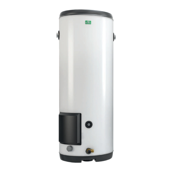
CTC Modul 300/400 E15 which we hope you will be very pleased with. On the CTC Modul 300/400 E15 is a power module. On its own, following pages, you will find information on how the the immersion heater is capable of, for example, heating system must be installed and maintained. -
Page 4: Safety Instructions
Safety instructions Turn off the power with an omnipolar switch before doing any work on the product. The product must be connected to a protective earth. The product is classified as IP44. The product must not be rinsed with water. When handling the product with a hoist ring or similar device, make sure that the lifting equipment, eyebolts and other parts are not damaged. - Page 5 Checklist The checklist must always be completed by the installer • In the event of servicing, this document may need to be provided • Installation must always be carried out according to the Installation and Maintenance Manual • Installation must always be carried out according to professional standards Following installation, the unit must be inspected and functional checks performed as indicated below: Pipe installation...
- Page 6 Serial number The serial number can be read from the barcode on the data plate. Digits 5 and 6 plus the last 6 digits make up the serial number.
-
Page 7: Important To Remember
Important to remember! Check the following points in particular on delivery and installation: Transportation • Transport CTC Modul to the installation site before removing the packaging. The product must be transported and stored in an upright position. Handle the product in the following manner: - Forklift truck - Lifting strap around the pallet. -
Page 8: System Components
Depending on needs and conditions and the layout of the installation space, a number of system components are required. The following system components can be obtained from CTC: CTC Modul 300/400 E15, power module • 1x stainless steel 282/380 litre tank •... -
Page 9: Technical Data/Energy Labelling
Technical data/energy labelling CTC Modul 400 L CTC Modul 300/400 E15 Technical data Article number 589802001 589800001/589801001 Electrical data 400 V 3 N~ 50 Hz IP class IP44 IP44 Volume (V) 282/380 Max. operating pressure (PS) kPa/bar Max. operating temperature (TS) °C... - Page 10 Dimensional drawing, CTC Modul 300 E15 KV inn VV ut Spiral Sensor 8021014 8021013 8021012 Article number Model Model Navn 589800001 CTC Modul 300 E15 8021013 CTC MODUL 300 E15 8021012 CTC MODUL 300 L 8021014 CTC MODUL 300 K30...
- Page 11 Dimensional drawing, CTC Modul 400 L, 400 E15 KV inn VV ut Spiral ut Sensor Spiral inn 8021008 8021007 8021009 8021011 Article number Model Model Navn 8021008 CTC MODUL 400 E15 589802001 CTC Modul 400 8021009 CTC MODUL 400 E30 589801001 CTC Modul 400 E15 8021007...
- Page 12 Pressure drop in tanks CTC Modul is series connected with a flange connection. The diagram shows the pressure drop in kPa in series connection depending on the flow and number of tanks connected in series (1–12). Important to remember regarding the flow through the tanks: The modules provide approx.
-
Page 13: Pipe Installation
Pipe installation General This chapter is for the person responsible for one or more of the necessary installations. Take your time going through functions and settings with the property owner and answer any questions. Installation must be performed by a qualified professional. Water quality Important! The tanks must be flushed... -
Page 14: Circulation Pumps
Installed on the incoming cold tap water line. Expansion vessel for cold tap water To avoid loss of overflow water (discharged during expansion of the water upon heating), an expansion vessel is installed in direct connection to the tanks' incoming cold tap water connection. The size of the vessel depends on the volume that has been selected in the system. -
Page 15: System Options
System options The module tank system is flexible and can be connected in different ways depending on needs and conditions. Some examples of connections are shown below. The system can be extended and adapted with an optional number of tanks as required. System 1 Connected heat pump with Legionella function 1 Storage module 400 L... - Page 16 Function The example in system 1 shows 3x 400 L storage tanks (1) and 2x 400 E15 power modules (2) (alternatively, further power modules can be connected in series). A heat pump (with EcoLogic (25) control system) connected via a charge exchanger (6) (pre)heats the tap water in the storage modules. A sensor (23) is installed on the lower part of the first storage module to start and stop accumulation of hot tap water.
- Page 17 HWC function A separate timer for HWC starts and stops the circulation pump (C) at the times when HWC is desired. The mixing valve (15) is supplied with the cooling hot tap return water, and mixes the hot tank water to the desired temperature. A solenoid valve (B) does not need to be installed if the hot tap water increase function (Legionella protection function) is not installed.
-
Page 18: System 2
System 2 Charging with an external hot water source, e.g. pellets etc., downstream charging. Storage module 400 L Connection of external heat 13 Manometer, cold tap water source (not heat pump) pressure Power module 400L 9 Electric additional heat 14 Expansion vessel Check valve (immersion heater) 15 Mixing valve, hot tap water... - Page 19 Charging with external heat source, e.g. pellets etc., upstream charging. 1 Storage module 400 L 7 Connection of external heat source pressure 2 Power module 400 E15 14 Expansion vessel 9 Electric additional heat (immersion heater) 15 Mixing valve, hot tap water 3 Check valve 11 Charge thermostat, external heat 16 Solenoid valve, charge circuit...
-
Page 20: Flange Couplings
Flange couplings The CTC flange coupling system provides a very compact and easy-to-install connection between products. Example of installation Double row Corner Single row... - Page 21 Significant hot water requirement/installations If the hot water requirement is very high, it may be necessary to connect the system in series/parallel as shown in the figure below. This reduces the pressure drop in the system. Make sure to install valves that enable adjustment of equal flow between the series-connected rows.
-
Page 22: Recommendations And Design
Recommendations and design During design, consumption is calculated over a 3 hour period with the following intervals: 1–5 apartments 240 l/apartment 6–10 apartments 220 l/apartment 11–15 apartments 200 l/apartment 16–20 apartments 190 l/apartment 21–25 apartments 180 l/apartment 26–35 apartments 175 l/apartment 36–45 apartments 165 l/apartment More than 45 apartments... - Page 23 Table 2 Energy content (usable hot water), as well as theoretically required charging power when charging from 10 to 75°C depending on required charge time. (High-temperature heat source). Total volume of storage tanks (L) 1200 1600 2000 2400 2800 Usable energy content, and also volume 40°C 1750 2600...
-
Page 24: Electrical Installation
Materials for connecting to 3x 5 kW are available in a supplementary Immersion heater 7.5 kW, CTC Modul 300/400 E15 package. The immersion heater consists of 3x 2.5 kW electrical heaters, which are switchable to 3x 5 kW. Installation, replacement and servicing of the product's immersion heater must be performed by a qualified electrical installer. -
Page 25: Wiring Diagram, Immersion Heater
Wiring diagram, immersion heater 7,5 kW, 400V + N 400V + N + PE 15 kW, 400V + N 400V + N + PE... -
Page 26: Commissioning
Commissioning Installation check Once installation is completed, review and tick off the items on the checklist (see section checklist). Flushing of tanks The corrosion resistance of the tanks must be ensured when the tanks enter service after the completed installation. The non-corrosive tanks are manufactured from high-quality stainless steel and, in order to achieve the best possible resistance against aggressive water, the tanks must be flushed with cold water before commissioning. -
Page 27: 10. Operation And Maintenance
10. Operation and maintenance After installation Once the system has been installed, the user and installer must together check that the system is in full working order. Let the installer show you where the power switches, controls, valves, fuses, safety vales etc. are so that you know how the system works and how it should be maintained. -
Page 28: Thermostat For Immersion Heater
11. Thermostat for immersion heater Operating temperature A combined operating/max thermostat is installed on the outer surface of the tank, close to the immersion heater. The thermostat controls the connection and disconnection of electrical power at the temperature that is set on the thermostat. Setting of the thermostat must be performed during electrical installation and must be performed/changed by a qualified electrical installer, as the space contains powered parts. -
Page 29: 12. Troubleshooting And Actions
12. Troubleshooting and actions The list below presumes that the installation is correctly dimensioned and has been functioning from the start. Fault has occurred "suddenly". Measures that involve intervention in the product must be performed by a qualified installer/service technician. Symptom Probable/possible fault Info/action... - Page 32 CTC AB Box 309 SE-341 26 Ljungby info@ctc.se +46 372 88 000 www.ctc.se...
Need help?
Do you have a question about the Modul 300 and is the answer not in the manual?
Questions and answers