Advertisement
Quick Links
Instruction Manual
D103759X012
July 2019
T205VB Series Vacuum Breakers
Table of Contents
Introduction .................................................................. 1
Specifications .............................................................. 2
Principle of Operation .................................................. 2
Installation ................................................................... 5
Startup, Adjustment and Shutdown ............................. 5
Maintenance ................................................................ 6
Parts Ordering ............................................................. 9
Parts List...................................................................... 9
Introduction
Scope of the Manual
This Instruction Manual provides instruction for
installation, startup, maintenance and parts lists for
Types T205VB and T205VBM vacuum breakers.
Instructions and parts lists for other equipment used
with these breakers are found in separate manuals.
Product Description
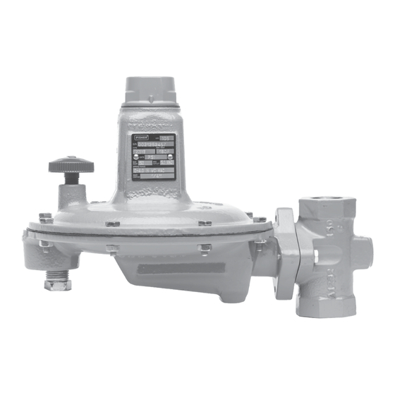
The T205VB Series vacuum breakers (Figure 1) are
used for precise control of small capacity, low-pressure
service applications where an increase
Figure 1. Typical Type T205VB Vacuum Breaker
in vacuum must be limited. These direct-operated
vacuum breakers are available in 3/4 and 1 in. / DN 20
and 25 body sizes and have 1/4 or 1/2 in. / 6.4 or
13 mm orifice.
The T205VB Series is available in two configurations:
Type T205VB for internal pressure registration
requiring no control line and Type T205VBM which
has a blocked throat and a control line connection for
external pressure registration.
T205VB Series
Advertisement

Subscribe to Our Youtube Channel
Related Manuals for Emerson Fisher T205VB Series


Summary of Contents for Emerson Fisher T205VB Series
-
Page 1: Table Of Contents
Instruction Manual T205VB Series D103759X012 July 2019 T205VB Series Vacuum Breakers Table of Contents Introduction ..............1 Specifications .............. 2 Principle of Operation ..........2 Installation ..............5 Startup, Adjustment and Shutdown ......5 Maintenance ..............6 Parts Ordering ............. 9 Parts List.............. -
Page 2: Specifications
Figure 2. An increase in vacuum (decrease local codes, rules and regulations in absolute pressure) is sensed on the under side and Emerson Process Management of the diaphragm, opening the disk assembly. This Regulator Technologies, Inc. permits positive pressure, atmosphere or an upstream (Emerson) instructions. - Page 3 T205VB Series VACUUM VACUUM VACUUM ADJUSTING SCREW VACUUM PUMP PUMP BEING BEING ADJUSTING SCREW ADJUSTING SCREW LIMITED LIMITED CONTROL SPRING DIAPHRAGM CONTROL CONTROL DIAPHRAGM VENT SPRING SPRING DIAPHRAGM STEM THROAT SEAL VALVE PLUG DISK VALVE PLUG DISK VENT VENT STEM STEM VALVE PLUG DISK CONTROL LINE...
- Page 4 T205VB Series Table 1. Vacuum Control Pressure Ranges VACUUM CONTROL SPRING WIRE DIAMETER SPRING FREE LENGTH SPRING PRESSURE RANGE (1)(2) SPRING COLOR PART NUMBER psig mbar 0 to 4 in. w.c. 0 to 10 0N039427222 Unpainted 0.062 3.06 0 to 1.0 0 to 69 0N086127022 Unpainted...
-
Page 5: Installation
T205VB Series Installation 2. This equipment may be installed in any position as long as the flow through the body is in the direction indicated by the arrow on the body. If WARNING continuous operation is required during inspection or maintenance, install a three-way bypass valve Personal injury, property damage, around the equipment. -
Page 6: Maintenance
(key 4) from or the requirements of local, state and federal the body (key 1). regulations. Due to the care Emerson takes in meeting all manufacturing requirements (heat treating, 2. Remove and inspect the body seal O-ring (key 11) dimensional tolerances, etc.), use only replacement... - Page 7 T205VB Series 4. Remove the cotter pin (key 15) if it is necessary 4. To replace the lever assembly (key 16), remove the to replace the disk holder assembly (key 13). For machine screws (key 17). Type T205VBM, also inspect the throat seal O-ring 5.
- Page 8 T205VB Series Type T205VBM correctly oriented, and secure them with the spring case cap screws (key 24) and hex nuts (key 23) to Key numbers are referenced in Figure 4. finger tightness only. 1. Remove the closing cap (key 22) and turn the 11.
-
Page 9: Parts Ordering
T205VB Series Parts Ordering Specify the eleven-character part number when When corresponding with the local Sales Office about ordering new parts from the following parts list. this vacuum breaker include the type number and all other pertinent information stamped on the nameplate. Parts List Description Part Number Description Part Number Spare Parts Kit (includes keys 10,... - Page 10 T205VB Series ERSA02739 APPLY LUBRICANT L1 = SILICONE GREASE L2 = ANTI-SEIZE LUBRICANT 1. Lubricants must be selected such that they meet the temperature requirements. Figure 3. Type T205VB Assembly...
- Page 11 T205VB Series ERSA02740 APPLY LUBRICANT L1 = SILICONE GREASE L2 = ANTI-SEIZE LUBRICANT 1. Lubricants must be selected such that they meet the temperature requirements. Figure 4. Type T205VBM Assembly...
- Page 12 Technologies, Inc. All rights reserved. 07/19. Emerson Automation Solutions The Emerson logo is a trademark and service mark of Emerson Electric Co. All other marks are the property of their prospective owners. Fisher™ is a mark owned by Fisher Controls International LLC, a...
Need help?
Do you have a question about the Fisher T205VB Series and is the answer not in the manual?
Questions and answers