Emerson Tartarini FL Series Instruction Manual
Pressure reducing regulators
Hide thumbs
Also See for Tartarini FL Series:
- Installation manual (10 pages) ,
- Instruction manual (25 pages) ,
- Instruction manual (52 pages)
Table of Contents
Advertisement
Quick Links
Download this manual
See also:
Installation Manual
Instruction Manual
D103068X012
August 2018
Type FL Pressure Reducing Regulators
WaRning
!
Failure to follow these instructions or
to properly install and maintain this
equipment could result in an explosion
and/or fire causing property damage and
personal injury or death.
Tartarini™ regulators must be installed,
operated and maintained in accordance
with federal, state and local codes, rules
and regulations and Emerson Process
Management Regulator Technologies,
inc. instructions.
if the regulator vents gas or a leak
develops in the system, service to
the unit may be required. Failure
to correct trouble could result in a
hazardous condition.
Call a gas service person to service the
unit. Only a qualified person must install
or service the regulator.
introduction
Scope of the Manual
This manual provides instructions for installation,
adjustment, maintenance and parts ordering
information for the Type FL regulators sold in
North America.
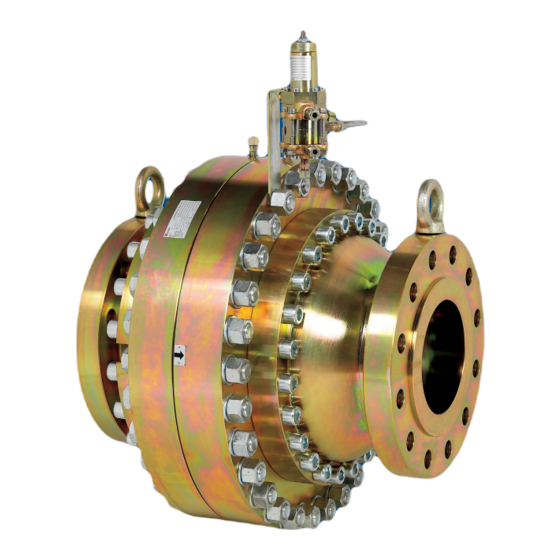
Figure 1. Type FL Regulator with PRX Series Pilot
Description
The Type FL is an accurate pilot-operated regulator
designed for high-pressure transmission/city gate, large
capacity distribution systems and power plant feeds.
The Type FL provides smooth, quiet operation, tight
shutoff and long life. The regulator is comprised of a
main valve actuator, a Type PRX/120 pressure reducing
pilot and a Type SA/2 pilot supply pressure regulator.
Type FL
Advertisement
Table of Contents

Related Manuals for Emerson Tartarini FL Series


Summary of Contents for Emerson Tartarini FL Series
- Page 1 Tartarini™ regulators must be installed, operated and maintained in accordance with federal, state and local codes, rules and regulations and Emerson Process Management Regulator Technologies, inc. instructions. if the regulator vents gas or a leak develops in the system, service to the unit may be required.
-
Page 2: Specifications
Type FL Specifications The Specifications section gives some general specifications for the Type FL regulators. The nameplates give detailed information for a particular regulator as it comes from the factory. Available Configuration Outlet Pressure Ranges See Table 1 Type FL: Pilot-operated pressure reducing regulator from 14.5 to 1160 psig / 1.00 to 80.0 bar Pressure Registration outlet pressures... - Page 3 Type FL TYPE PRX/120 TYPE SA/2 E0827_01/2016 TYPE FL TYPE PRX/120 TYPE PRX/131 TYPE SA/2 TYPE FL WiTh TYPE PRX/131 QUiCK DUMP PiLOT M1216_08/2018 inLET PRESSURE OUTLET PRESSURE TYPE PRX/120: INLET PRESSURE S - BLEED PORT TYPE Sa/2: LOaDing PRESSURE B - SUPPLY PORT V - SEnSing PORT OUTLET PRESSURE...
- Page 4 Type FL TYPE TYPE PRX/120 PRX/120 TYPE TYPE SA/2 SA/2 M1204_01/2016 TYPE FL WiDE-OPEn MOniTOR TYPE PRX/125 TYPE TYPE PRX/120 TYPE TYPE PRX/120 SA/2 SA/2 M1201_01/2016 inLET PRESSURE OUTLET PRESSURE TYPE PRX: aTMOSPhERiC PRESSURE S - BLEED PORT TYPE Sa/2: LOaDing PRESSURE B - SUPPLY PORT V - SEnSing PORT...
-
Page 5: Principle Of Operation
Type FL TYPE PRX/120 TYPE PRX/120 TYPE PRX/131 TYPE SA/2 TYPE SA/2 M1212_08/2018 inLET PRESSURE OUTLET PRESSURE INLET PRESSURE TYPE PRX: S - BLEED PORT TYPE Sa/2: aTMOSPhERiC PRESSURE OUTLET PRESSURE B - SUPPLY PORT V - SEnSing PORT LOaDing PRESSURE ATMOSPHERIC PRESSURE L - LOaDing PORT R - PiLOT SEnSing PORT... -
Page 6: Monitoring Systems
Type FL Monitoring Systems Working Monitoring Regulators (Figure 3) In a working monitoring system, the upstream Monitoring regulation is overpressure protection by regulator requires two pilots and it is always the containment, therefore, there is no relief valve to vent to the atmosphere. - Page 7 Type FL SPaCER DETaiLS SPaCER DETaiLS FOR FOR SiZES SMaLLER Than nPS 6 TO 12 / Dn 150 TO 300 nPS 6 / Dn 150 E0831 OUTLET FLangE (KEY 22) SOCKET hEaD SCREW (KEY 5 OUTLET SiDE) DiSK-hOLDER (KEY 19) E0832 O-Ring (KEY 4 OR 18 DEPEnDing On SiZE)
-
Page 8: All Installations
Type FL additionally, physical damage to the 5. Connect inlet supply pressure to the Type SA/2 regulator could break the pilot off the 1/4 NPT inlet, Port M. main valve, causing personal injury and property damage due to bursting WaRning of pressure-containing parts. - Page 9 Type FL 3. Connect a control (sense) line from the “A” port CaUTiOn of the upstream working PRX Series pilot to the intermediate pressure portion of piping, using To prevent damage to the pilot during 3/8 in. / 9.5 mm or larger outside diameter tubing. startup, the sense and bleed lines 4.
-
Page 10: Pilot Adjustment
Type FL Startup setpoint higher than the Type PRX/120 monitor pilot. Set the Type PRX/120 monitor pilot to the desired 1. Make sure all block valves, vent valves and setpoint of the Type PRX/131 pilot, which should be control line valve(s) are closed. 5 to 10 psi / 0.34 to 0.69 bar above the monitor pilot setpoint. -
Page 11: Maintenance
Type FL The Restrictor and Damper screws on the PRX Series system and release all pressure from the pilot control the regulator’s proportional band (droop) pilot and main valve before performing and speed of response. To tune, follow the steps maintenance operations. - Page 12 Type FL TOP ViEW TOP ViEW LEgaCY TRaVEL inDiCaTOR DETaiL iMPROVED TRaVEL inDiCaTOR DETaiL P1764 aPPLY LUBRiCanT (L) / SEaLanT (S) L1 = LiThiUM hYDROXYSTEgRaTE nLgi 2 gRaDE gREaSE S1 = anaEROBiC METhaCRYLaTE SEaLanT FOR nUTS anD BOLTS 1. Lubricant and sealant must be selected such that they meet the temperature requirements. Figure 5.
- Page 13 Type FL 6. Slide the travel indicator bushing (key 38) over the 10. Insert machine screws (key 10) in the lower travel indicator stem (key 34) and tighten firmly in cover (key 21) and tighten uniformly to ensure place with a torque of 3.7 ft-lbs / 5.0 N•m. proper seal.
-
Page 14: Parts Ordering
Type FL 14. Screw in adjusting screw (key 1) at desired spring 3. Remove and inspect O-ring (key 13) for damage or compression and use the lock nut (key 2) to lock wear and replace if necessary. Lightly lubricate the the adjusting screws position. -
Page 15: Parts List
Type FL Parts List Type FL Main Valve (Figure 6) Description Part number Description Part number Start-Up Repair Kit (includes keys 18, 20, 46 Socket Head Screw and 47. Key 46 is only used for NPS 1 / DN 25 (16 required) M5011044X12 NPS 2 / DN 50 (16 required) M5011062X12... - Page 16 Type FL Type FL Main Valve (Figure 6) (continued) Description Part number Description Part number Washer Disk (continued) NPS 1 / DN 25 (16 required) M5001007X12 Type FL, FL-SR, FL-SR/SRS (continued) NPS 2 / DN 50 (16 required) M5001009X12 Fluorocarbon (FKM) NPS 3 / DN 80 (16 required) M5001012X12 NPS 1 / DN 25...
- Page 17 Type FL Type FL Main Valve (Figure 6) (continued) Description Part number Description Part number Outlet Flange Spacer (continued) Type FL, FL-SR or FL-SRII only Type FL-SR/SRS or FL-SRII/SRS CL300 RF CL300 RF NPS 1 / DN 25 M0268290X12 NPS 1 x 4 / DN 25 x 100 M0208100X12 NPS 2 / DN 50 M0268420X12...
- Page 18 Type FL Type FL Main Valve (Figure 6) (continued) Description Part number Description Part number O-ring Indicator Cover Nitrile (NBR) NPS 1 / DN 25 M0194580X12 NPS 1 / DN 25 M6010104X12 NPS 2 / DN 50 M0194710X12 NPS 2 / DN 50 M6010116X12 NPS 3 / DN 80 M0192220X12...
- Page 19 Type FL Type FL Main Valve (Figure 6) (continued) Description Part number Description Part number Screw Ring (continued) NPS 8 / DN 200 only (6 required) M5007160X12 CL600 RF NPS 10 / DN 250 (6 required) ERCA04505A0 NPS 1 / DN 25 M0272900X12 Washer NPS 2 / DN 50...
- Page 20 Type FL Type SRS Main Valve (Figure 8) (continued) Description Part number Description Part number Rod (6 required) Stem M0253430X12 NPS 6 / DN 150 ERAA17099A0 Nameplate M0268080X12 Plate #2 Stem O-ring NPS 6 / DN 150 ERAA16864A0 Nitrile (NBR) M6010223X12 Plate #3 (2 required) Fluorocarbon (FKM)
- Page 21 Type FL Table 3. Type FL Start-Up Repair Kit Part Numbers DESCRiPTiOn DiSK MaTERiaL nPS 1 / Dn 25 nPS 2 / Dn 50 nPS 3 / Dn 80 nPS 4 / Dn 100 nPS 6 / Dn 150 nPS 8 / Dn 200 nPS 10 / Dn 250 Nitrile (NBR) M2600750X12 M2600754X12...
- Page 22 Type FL 37B 35 nPS 1 TO 4 / Dn 25 TO 100 23 24 37B 35 nPS 6 / Dn 150 Figure 6. Type FL Main Valve Assembly...
- Page 23 Type FL 12 13 14 40 34 38 36 66 37B 35 33 31 32 31 30 29 LM/1403 nPS 8 / Dn 200 Figure 6. Type FL Main Valve Assembly (continued)
- Page 24 Type FL 31 32 29 30 31 13 14 15 nPS 10 / Dn 250 Figure 6. Type FL Main Valve Assembly (continued)
- Page 25 Type FL nPS 1 anD 2 / Dn 25 anD 50 nPS 3, 4 anD 6 / nPS 8 / Dn 200 nPS 10 / Dn 250 WiThOUT SiLEnCER Dn 80, 100 anD 150 WiThOUT SiLEnCER WiThOUT SiLEnCER WiThOUT SiLEnCER nPS 1 anD 2 / Dn 25 anD 50 nPS 3, 4 anD 6 / Dn 80, 100 anD 150 nPS 1 anD 2 / Dn 25 anD 50...
- Page 26 Type FL ERSA03388 ERSA03393 nPS 1 anD 2 / Dn 25 anD 50 WiThOUT SiLEnCER nPS 3 TO 6 / Dn 80 TO 150 WiThOUT SiLEnCER ERSA03396 nPS 8 TO 10 / Dn 200 TO 250 WiThOUT SiLEnCER ERSA03389 ERSA03394 nPS 1 anD 2 / Dn 25 anD 50 nPS 3 TO 6 / Dn 80 TO 150 WiTh TYPE SR...
- Page 27 Type FL ERSA03390 ERSA03392 nPS 1 anD 2 / Dn 25 anD 50 nPS 3 TO 6 / Dn 80 TO 150 WiTh TYPE SRii WiTh TYPE SRii ERSA03450 nPS 8 TO 10 / Dn 200 TO 250 WiTh TYPE SRii Figure 7.
- Page 28 Type FL 202 203 23 24 SPaCER DETaiLS FOR nPS 6 TO 12 / Dn 150 TO 300 211 210 206 209 208 206 SPaCER DETaiLS FOR SiZES SMaLLER Than nPS 6 / Dn 150 nPS 1 TO 4 / Dn 25 TO 100 TORQUE: 29.5±3.7 ft-lbs / 40±5 N•m...
- Page 29 Type FL 206 207 nPS 8 / Dn 200 Figure 8. Type SRS Assembly (continued)
- Page 30 Type FL “L” PORT TYPE PRX/120 “a” PORT “B” PORT TYPE Sa/2 GE46220_A nPS 1 anD 2 / Dn 25 anD 50 Figure 9. Type FL Single Pilot Mounting Assembly...
- Page 31 Type FL “L” PORT “B” PORT TYPE PRX/120 “a” PORT TYPE Sa/2 GE45181_B nPS 3 anD 4 / Dn 80 anD 100 Figure 9. Type FL Single Pilot Mounting Assembly (continued)
- Page 32 Type FL “L” PORT “B” PORT “a” PORT TYPE PRX/120 TYPE Sa/2 GE45213_B nPS 6 anD 8 / Dn 150 anD 200 Figure 9. Type FL Single Pilot Mounting Assembly (continued)
- Page 33 Type FL “B” PORT “L” PORT “S” PORT “L” PORT “B” PORT “a” PORT TYPE PRX/120-aP TYPE PRX/131-aP TYPE Sa/2 nOTE: TYPE PRX/131 BOOSTER VaLVE iS inSTaLLED aS STanDaRD FOR nPS 10 / Dn 250 nPS 10 / Dn 250 Figure 9.
- Page 34 Type FL TYPE PRX/131 OR PRX/131-aP aSSEMBLY TYPE PRX/120 OR PRX/125 SECTiOn a-a Figure 10. PRX Series Pilot Assembly...
- Page 35 Type FL TYPE PRX/125 OR PRX/125-aP TYPE PRX/120 OR PRX/120-aP TYPE PRX/120-aP OR PRX/125-aP Figure 10. PRX Series Pilot Assembly (continued) Table 9. Type PRX/120 Connections CODE PORT DESCRiPTiOn Downstream Sense Line Pilot feed Outlet discharge To regulator loading pressure chamber...
- Page 36 Technologies, Inc. All rights reserved. 08/18. Emerson Automation Solutions The Emerson logo is a trademark and service mark of Emerson Electric Co. All other marks are the property of their prospective owners. Tartarini™ is a mark owned by O.M.T. Officina Meccanica...
Need help?
Do you have a question about the Tartarini FL Series and is the answer not in the manual?
Questions and answers