Table of Contents
Advertisement
Quick Links
172-65613A-03 (DR8-3P/DR8-3EP/DR8-6P/DR8-6EP) 11 June 2020
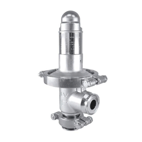
Clean Steam Direct-acting Pressure Reducing Valve
DR8-3P / DR8-3EP
DR8-6P / DR8-6EP
Manufacturer
881 Nagasuna, Noguchi, Kakogawa, Hyogo, 675-8511, Japan
Tel: [81]-(0)79-422-1122 Fax: [81]-(0)79-422-0112
Copyright © 2020 by TLV CO., LTD. All rights reserved
Advertisement
Table of Contents

Related Manuals for TLV DR8-3P


Summary of Contents for TLV DR8-3P
- Page 1 172-65613A-03 (DR8-3P/DR8-3EP/DR8-6P/DR8-6EP) 11 June 2020 Clean Steam Direct-acting Pressure Reducing Valve DR8-3P / DR8-3EP DR8-6P / DR8-6EP Manufacturer 881 Nagasuna, Noguchi, Kakogawa, Hyogo, 675-8511, Japan Tel: [81]-(0)79-422-1122 Fax: [81]-(0)79-422-0112 Copyright © 2020 by TLV CO., LTD. All rights reserved...
-
Page 2: Table Of Contents
Troubleshooting .............. 19 EXPRESS LIMITED WARRANTY ......21 Introduction Thank you for purchasing the TLV DR8 clean steam direct-acting pressure reducing valve. This product has been thoroughly inspected before being shipped from the factory. When the product is delivered, before doing anything else, check the specifications and external appearance to make sure nothing is out of the ordinary. -
Page 3: Safety Considerations
The three types of cautionary items above are very important for safety: be sure to observe all of them as they relate to installation, use, maintenance, and repair. Furthermore, TLV accepts no responsibility for any accidents or damage occurring as a result of failure to observe these precautions. - Page 4 Use only under conditions in which no water hammer will occur. The impact of water hammer may damage the product, leading to fluid discharge, which may cause burns or other injury. 172-65613A-03 (DR8-3P/DR8-3EP/DR8-6P/DR8-6EP) 11 Jun 2020...
-
Page 5: Specifications
(60 to 115 psig) 0.018 to 0.3 MPaG 0.27 to 0.6 MPaG (2.5 to 45 psig) (40 to 85 psig) Adjustable Pressure Range No more than a maximum of 75% of the primary pressure (1MPa = 10.197 kg/cm 172-65613A-03 (DR8-3P/DR8-3EP/DR8-6P/DR8-6EP) 11 Jun 2020... -
Page 6: Correct Usage Of The Dr8 Direct-Acting Pressure Reducing Valve
If the safety valve is installed between the DR8 and a control valve, an eventual pressure rise could activate the safety valve. 172-65613A-03 (DR8-3P/DR8-3EP/DR8-6P/DR8-6EP) 11 Jun 2020... - Page 7 (Two- stage pressure reduction) Less than 30 d or more 30 d (Example: if nominal size is Steam Steam 25 mm (1 in), have 750 Trap Trap mm (30 in) or more) 172-65613A-03 (DR8-3P/DR8-3EP/DR8-6P/DR8-6EP) 11 Jun 2020...
-
Page 8: Configuration
1 piece Number of parts: 2 pieces Number of parts for sizes 15 to 20 mm ( in): 4 pieces, 25 mm (1 in): 2 pieces For sizes 15 to 20 mm ( only 172-65613A-03 (DR8-3P/DR8-3EP/DR8-6P/DR8-6EP) 11 Jun 2020... -
Page 9: Installation
It is recommended that the inlet and DR-8 outlet pipes be supported securely. Piping 4. Maintenance Space Support Piping Leave sufficient space for maintenance, Support inspection and repair. A: 260 mm (10 B: 110 mm (4 172-65613A-03 (DR8-3P/DR8-3EP/DR8-6P/DR8-6EP) 11 Jun 2020... - Page 10 Pressure Side Valve Gauge Inlet Steam Trap Pressure Valve Steam Trap Gauge Bypass Valve Safety Valve (Relief Valve) Pressure Reducing Valve Secondary Side Primary Outlet Pressure Side Valve Gauge Pressure Inlet Gauge Steam Trap Valve 172-65613A-03 (DR8-3P/DR8-3EP/DR8-6P/DR8-6EP) 11 Jun 2020...
- Page 11 To perform blowdown, close the inlet valve (A) first, then the outlet valve (B), and open the bypass valve (C). Do not open valves too quickly. Bypass Valve Safety (Relief) Valve Outlet Valve DR-8 Pressure Gauge Secondary Side Pressure Primary Gauge Side Inlet Valve Steam Steam Trap Trap 172-65613A-03 (DR8-3P/DR8-3EP/DR8-6P/DR8-6EP) 11 Jun 2020...
-
Page 12: Adjustment
8. After setting, hold the adjustment screw and retighten the locknut. 9. When shutting down the system, always close the outlet shut-off valve first and then the inlet valve. (If the inlet shut-off valve is closed first, the safety valve may be tripped.) 172-65613A-03 (DR8-3P/DR8-3EP/DR8-6P/DR8-6EP) 11 Jun 2020... -
Page 13: Maintenance
If hunting or chattering takes place, cracks or fatigue may develop in Protective Sheet a short period of time. Valve, Body If there is chattering or dirt, premature wear may result. Valve Guide, If hunting or chattering takes place, premature wear may result. (Slide Bearing) 172-65613A-03 (DR8-3P/DR8-3EP/DR8-6P/DR8-6EP) 11 Jun 2020... -
Page 14: Disassembly
Then remove the from the piping, and secure it in a vise to perform the inspection. Disassembling the Adjustment Section Loosen the cap and the locknut first. Loosen the adjustment screw completely and remove the body clamp. 172-65613A-03 (DR8-3P/DR8-3EP/DR8-6P/DR8-6EP) 11 Jun 2020... - Page 15 Hold the valve in place with an adjustable wrench across the flats on the upper part of the valve and use another wrench to remove the high nut. After removing the high nut, remove the plain washer, the upper diaphragm retainer and the diaphragm. 172-65613A-03 (DR8-3P/DR8-3EP/DR8-6P/DR8-6EP) 11 Jun 2020...
- Page 16 Remove the adapter and the inlet clamp gasket. (for sizes 15 to 20 mm ( in) only) Separate the valve guide from the body. The valve comes off with the valve guide. Valve Inlet Clamp Gasket Valve Guide 172-65613A-03 (DR8-3P/DR8-3EP/DR8-6P/DR8-6EP) 11 Jun 2020...
- Page 17 (for sizes 15 to 20 mm ( in) only) NOTE: Avoid using solvent to clean these parts as it may accelerate deterioration of the diaphragm, protective sheet, and resin part of the valve guide and retainer gasket. 172-65613A-03 (DR8-3P/DR8-3EP/DR8-6P/DR8-6EP) 11 Jun 2020...
- Page 18 ** The slide bearing and snap ring cannot be removed individually as they are incorporated with the valve guide and must be replaced as a set with the valve guide. 172-65613A-03 (DR8-3P/DR8-3EP/DR8-6P/DR8-6EP) 11 Jun 2020...
-
Page 19: Reassembly
(2.2) Body Clamp Nut, (2.2) Inlet Clamp Nut (1 Nm 10 kgcm) NOTE: If drawings or other special documentation were supplied for the product, any torque given there takes precedence over values shown here. 172-65613A-03 (DR8-3P/DR8-3EP/DR8-6P/DR8-6EP) 11 Jun 2020... -
Page 20: Troubleshooting
Check the flow rate, re-set the large pressure; check the model selection, replace with a more suitable unit if necessary* The adjustment screw has Replace with a new seized adjustment screw *For model selection and replacement, contact TLV. 172-65613A-03 (DR8-3P/DR8-3EP/DR8-6P/DR8-6EP) 11 Jun 2020... - Page 21 *For model selection and replacement, contact TLV. NOTE: When replacing parts with new, use the parts list for reference and replace with parts from the Maintenance Kit, Repair Kit, etc. (Please note that replacement parts are only available in pre-packaged kits.)
-
Page 22: Express Limited Warranty
Subject to the limitations set forth below, TLV Corporation, a North Carolina corporation (“TLV”) warrants that products which are sold by it, TLV CO., LTD., a Japanese corporation (“TLVJ”) or TLV International, Inc., a Japanese corporation (“TII”), which products (the “Products”) are designed and manufactured by TLVJ, conform to the specifications published by TLV for the corresponding part numbers (the “Specifications”) and are free from defective workmanship and... - Page 23 TRANSPORTATION COSTS ASSOCIATED WITH THE RETURN OR REPLACEMENT OF THE CLAIMED DEFECTIVE PRODUCT ARE SOLELY THE RESPONSIBILITY OF BUYER OR THE FIRST END USER. TLV RESERVES THE RIGHT TO INSPECT ON THE FIRST END USER’S SITE ANY PRODUCTS CLAIMED TO BE DEFECTIVE BEFORE ISSUING A RETURN MATERIAL AUTHORIZATION.
Need help?
Do you have a question about the DR8-3P and is the answer not in the manual?
Questions and answers