Table of Contents
Advertisement
Available languages
Available languages
Quick Links
INSTRUCTION MANUAL
Keep this manual in a safe place for future reference
DIRECT-ACTING PRESSURE REDUCING
VALVES FOR STEAM AND/OR AIR
MODEL DR20/A-DR20
EINBAU- UND BETRIEBSANLEITUNG
Gebrauchsanleitung leicht zugänglich aufbewahren
DIREKT WIRKENDE DRUCKREDUZIERVENTILE
FÜR DAMPF UND/ODER DRUCKLUFT
TYP DR20/A-DR20
MANUEL D UTILISATION
Conserver ce manuel dans un endroit facile d'accès
DÉTENDEUR-RÉGULATEURS À ACTION
DIRECTE POUR VAPEUR ET/OU AIR
MODÈLE DR20/A-DR20
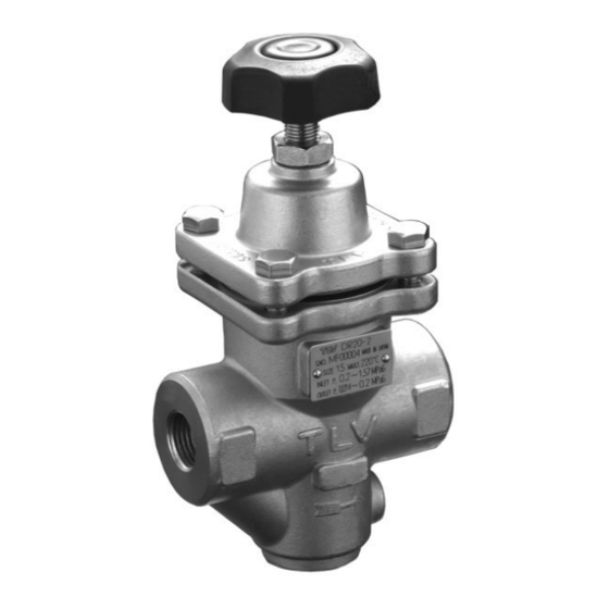
DR20
A-DR20
Copyright (C)
by TLV CO., LTD. All rights reserved.
Advertisement
Table of Contents

Subscribe to Our Youtube Channel
Related Manuals for TLV DR20


Summary of Contents for TLV DR20
- Page 1 DIREKT WIRKENDE DRUCKREDUZIERVENTILE FÜR DAMPF UND/ODER DRUCKLUFT TYP DR20/A-DR20 MANUEL D UTILISATION Conserver ce manuel dans un endroit facile d'accès DÉTENDEUR-RÉGULATEURS À ACTION DIRECTE POUR VAPEUR ET/OU AIR MODÈLE DR20/A-DR20 DR20 A-DR20 Copyright (C) by TLV CO., LTD. All rights reserved.
- Page 2 Keep the manual in a safe place for future reference. The DR20 direct-acting pressure reducing valve for steam and air is capable of reducing from primary pressures of between 0.2 and 1.6 MPaG (30 – 230 psig) to secondary pressures between 0.014 and 1.0 MPaG (2 –...
-
Page 3: Safety Considerations
• The three types of cautionary items above are very important for safety; be sure to observe all of them, as they relate to installation, use, maintenance, and repair. Furthermore, TLV accepts no responsibility for any accidents or damage occurring as a result of failure to observe these precautions. - Page 4 • Diese drei Warnzeichen sind wichtig für Ihre Sicherheit. Sie müssen unbedingt beachtet werden, um den sicheren Gebrauch des Produktes zu gewährleisten und Einbau, Wartung und Reparatur ohne Unfälle oder Schäden durchführen zu können. TLV haftet nicht für Unfälle oder Schäden, die durch Nichtbeachtung dieser Sicherheitshinweise entstehen.
-
Page 5: Règles De Sécurité
• Ces 3 indicateurs sont importants pour votre sécurité; observez les précautions de sécurité énumérées dans ce manuel pour l’installation, l’utilisation, l'entretien et la réparation du produit. TLV n’accepte aucune responsabilité en cas d’accident ou de dommage survenant à la suite d'un non-respect de ces précautions. - Page 6 Für A-DR20: Die Ventilsitzdichtung ist aus Kunststoff (Standard: Kunststoff) und als Einlage im Hauptventil integriert. Pour le A-DR20: Le caoutchouc (en standard: fluorine) est utilisé sur la surface d'usure. Le caoutchouc est serti dans la vanne principale. Soft Seat (Fluorine rubber)
- Page 7 Cannot be removed individually as it is incorporated with the spacer and must be replaced as a set with the spacer. For A-DR20: The rubber is inlaid in the main valve and cannot be removed. The main valve itself must be replaced.
- Page 8 Verwendbare Medien is omitted from the nameplate when there are no options. Fluide applicables Die Valve No. wird angegeben bei Typen mit Optionen. DR20 A-DR20 Bei Typen ohne Optionen bleibt diese Stelle frei. Steam, Air Le Valve No. est indiqué pour des modèles avec options.
-
Page 9: Piping And Installation
5. Piping and Installation • Installation, inspection, maintenance, repairs, disassembly, adjustment and CAUTION valve opening/closing should be carried out only by trained maintenance personnel. • Take measures to prevent people from coming into direct contact with product outlets. • Install for use under conditions in which no freeze-up will occur. •... - Page 10 If an on-off valve is required to stop the supply of steam or air to the equipment, install it on the inlet side of the DR20/A-DR20. If a solenoid valve is installed at the outlet of the DR20/A-DR20, it will cause heavy chattering and may lead to damage of the DR20/A-DR20. (When the on-off valve...
- Page 11 5.7 Piping Supports / Maintenance Space Install the Leave sufficient DR20/A-DR20, paying space for attention to avoid maintenance, excessive load, inspection and bending and vibration. repair. Supporting the inlet and outlet pipes securely is recommended. (6″ ) (6″ ) 5.8 Piping Size / Diffuser If the secondary side flow velocity is expected to be more than 30 m/s (100 ft/s), install a diffuser in order to keep the flow velocity below 30 m/s (100 ft/s).
- Page 12 Loosen the locknut adjustment handle 4. Slowly, fully open the shut-off valve at the inlet of the DR20/A-DR20. 5. Slightly open the shut-off valve at the outlet of the DR20/A-DR20. 6. Turn the adjustment handle clockwise until the desired outlet pressure is obtained. Wait several minutes.
-
Page 13: Inspection And Maintenance
Check for warping or damage Gaskets Wait for the body to cool before attempting to remove the DR20/A-DR20 from the line. Then remove the DR20/A-DR20 from the piping and secure it in a vise to perform the inspection. 7.1 Disassembling the Adjustment Section... - Page 14 Body spring and the screen. Main Valve* * For A-DR20: The rubber is inlaid in the main valve and cannot be removed. The main valve itself must be replaced. 7.4 Cleaning After inspection and removal of any abnormality, clean and reassemble the parts.
-
Page 15: Troubleshooting
This product is shipped after stringent checks and inspection, and should perform its intended function for a long period of time without failure. However, should there be any problem encountered in the operation of the DR20/A-DR20, Consult the troubleshooting guide below. Problem... -
Page 16: Rohrleitungsführung Und Einbauhinweise
5. Rohrleitungsführung und Einbauhinweise • Einbau und Ausbau, Inspektion, Wartungs- und Reparaturarbeiten, VORSICHT Öffnen/Schließen von Armaturen, Einstellung von Komponenten, dürfen nur von geschultem Wartungspersonal vorgenommen werden. • In sicherer Entfernung von Auslassöffnungen aufhalten und andere Personen warnen, sich fern zu halten. •... - Page 17 Magnetventils auf der Austrittsseite von DR20/A-DR20 kann zu heftigen Schwingungen bzw. Druckstößen führen, die eine Beschädigung von DR20/A-DR20 bewirken können (wenn ein AUF/ZU-Ventil öffnet, ändert sich der Minderdruck von DR20/A-DR20 von 0 auf Einstelldruck, und durchläuft dabei ein Reduktionsverhältnis unterhalb 1:30, was mit DR20/A-DR20 nicht regelbar ist.
- Page 18 DR20/A-DR20 und dem Verbraucher groß ist, muss der entsprechende Druckverlust bei der Auslegung der Leitung beachtet werden. Rohrerweiterung Länge gerader Leitung 10 d oder länger vor DR20/A-DR20, 15 d oder länger nach DR20/A-DR20 5.9 Druckreduzierung in 2 Stufen Die Druckreduzierung in zwei Stufen wird empfohlen, wenn der benötigte Minderdruck wegen der vorliegenden Betriebsbedingungen mit nur einem Druckminderventil nicht erreicht werden kann.
- Page 19 6. Einstellung Die beschriebenen Schritte zur Einstellung von DR20/A-DR20 befolgen. Besonders in einem Dampfsystem muss das Druckminderventil DR20 sorgfältig eingestellt werden, um den Dampfverbraucher vor Wasserschlag zu schützen 1. Vor Beginn müssen alle Rohrleitungen durchgeblasen werden. Das Durchblasen ist besonders wichtig wenn die Leitungen längere Zeit außer Betrieb waren.
-
Page 20: Inspektion Und Wartung
Auf Verformung, Risse und Beschädigung prüfen. Dichtungen Auf Verformung oder Beschädigung prüfen Warten, bis das Gehäuse abgekühlt ist. Dann DR20/A-DR20 aus der Rohrleitung ausbauen und zur Inspektion in einen Schraubstock spannen. 7.1 Ausbau der Teile im Einstell-Bereich Die Kontermutter lösen und den Einstellgriff vollständig herausschrauben. - Page 21 Hauptventil, Druckfeder und Schmutzsieb aus dem Gehäuse Gehäuse herausnehmen. Hauptventil* * Für A-DR20: Die Kunststoffeinlage im Hauptventil kann nicht entnommen werden. Zum Austausch das Hauptventil ersetzen. 7.4 Reinigung Nach Inspektion und Wartung alle Teile reinigen und das Ventil zusammenbauen. Die folgenden Teile müssen gereinigt werden...
-
Page 22: Fehlersuche
8. Fehlersuche Unsere Druckminderventile werden einer strengen Endkontrolle mit einer genauen Funktions- prüfung unterzogen. Sollte jedoch trotzdem eine Störung am Druckminderventil DR20/A-DR20 auftreten, gehen Sie bitte nach der folgenden Anleitung vor. Fehler Ursache Gegenmaßnahmen Kein Dampf/keine Luft vorhanden Einlass-/Auslassleitungen und Einlass- Minderdruck /Auslassventil überprüfen... - Page 23 5. Tuyautage et installation correcte • Tout installation, inspection, entretien, réparation, démontage, ajustement et ATTENTION ouverture/fermeture de vanne doit être fait uniquement par une personne formée à l'entretien. • Eviter que des personnes n'entrent en contact direct avec les orifices du produit. •...
- Page 24 Si une soupape de contrôle ouvert/fermé est requise pour stopper l’alimentation de vapeur ou d’air du système, il faut l’installer du côté entrée du DR20/A-DR20. Si une soupape à commande par solénoïde est installée à la sortie du détendeur, elle entraînera un claquement important et pourrait endommager le piston et la soupape principale.(Lorsque la soupape de contrôle...
- Page 25 5.7 Support des conduites / Espace d’inspection Installer le Laisser DR20/A-DR20 en suffisamment prenant soin d’éviter d’espace pour toute charge excessive, pouvoir effectuer courbure ou vibration. les inspections et Nous vous les réparations. recommandons de supporter fermement les conduites d’entrée et de sortie.
- Page 26 6. Ajustement Veuillez suivre les procédures suivantes pour régler le DR20/A-DR20. Surtout si le détendeur DR20 est installé sur un système vapeur, il doit être correctement ajusté afin de protéger l'équipement contre les coups de belier. 1. Il est indispensable de purger toutes les conduites à fond.
-
Page 27: Contrôle Et Entretien
Joints Vérifier qu’ils ne soient ni gondolés ni endommagés Attendre que le corps du DR20/A-DR20 soit refroidi avant de le retirer des conduites. Retirer ensuite le DR20/A-DR20 des conduites et l’attacher dans un étau pour faire l’inspection. 7.1 Démontage de la section d’ajustement Dévisser le contre-écrou et desserrer... - Page 28 Corps et la crépine. Soupape principale* * Pour le A-DR20: Le caoutchouc est serti dans la vanne principale et ne peut être enlevé. La vanne principale doit être remplacée. 7.4 Nettoyage Après l’inspection, et après avoir retiré toute anormalité, nettoyer et rassembler les pièces. Les pièces suivantes doivent être nettoyées avant le rassemblage:...
-
Page 29: Détection Des Problèmes
Ce produit est expédié après avoir subi de nombreux tests et une inspection rigoureuse. Il devrait remplir ses fonctions pendant une longue période de temps, sans défaillance. Toutefois, si un problème devait survenir pendant le fonctionnement du DR20/A-DR20, consulter le guide de détection des problèmes ci-dessous. -
Page 30: Product Warranty
9. Product Warranty 1) Warranty Period: one year after product delivery. 2) TLV CO., LTD. warrants this product to the original purchaser to be free from defective materials and workmanship. Under this warranty, the product will be repaired or replaced at our option, without charge for parts or labor. - Page 31 For Service or Technical Assistance: Contact your representative or your regional office. Für Reparatur und Wartung: Wenden Sie sich bitte an Ihre Vertretung oder an eine der Niederlassungen. Pour tout service ou assistance technique: Contactez votre agent ou votre bureau régional USA and Canada: T e l: [1]-704-597-9070 USA und Kanada:...
- Page 32 Manufacturer: T e l : [81]-(0)79-422-1122 Hersteller: 881 Nagasuna, Noguchi, Kakogawa, Fax: [81]-(0)79-422-0112 Fabricant: Hyogo 675-8511, Japan Printed on recycled paper. Auf Recycling-Papier gedruckt. Imprimé sur du papier recyclé. PAC-65334-egf Rev. 3/2018 (M)
Need help?
Do you have a question about the DR20 and is the answer not in the manual?
Questions and answers