Table of Contents
Advertisement
Quick Links
Advertisement
Table of Contents

Subscribe to Our Youtube Channel
Related Manuals for TLV DR8-3P


Summary of Contents for TLV DR8-3P
- Page 1 ISO 9001 ISO14001 Manufacturer Kakogawa, Japan is approved by LRQA Ltd. to ISO 9001/14001 Instruction Manual Clean Steam Direct-Acting Pressure Reducing Valve Featured Models: DR8-3P/DR8-3EP/DR8-6P/DR8-6EP 172-65613M-08 Publication date 8 November 2023 Copyright © 2023 TLV CO., LTD.
-
Page 2: Table Of Contents
Acceptable Operating Range ....................7 Correct usage of the product ....................8 Configuration .......................... 11 Installation ..........................13 Adjustment ..........................16 Maintenance ........................... 17 Disassembly ........................... 18 Reassembly ..........................23 Troubleshooting ........................24 TLV EXPRESS LIMITED WARRANTY ................... 27 Service ........................... 29... -
Page 3: Introduction
Introduction Thank you for purchasing the TLV DR8 clean steam direct-acting pressure reducing valve. This product has been thoroughly inspected before being shipped from the factory. When the product is delivered, before doing anything else, check the specifications and external appearance to make sure nothing is out of the ordinary. -
Page 4: Safety Considerations
• The three types of cautionary items above are very important for safety: be sure to observe all of them as they relate to installation, use, maintenance and repair. Furthermore, TLV accepts no responsibility for any accidents or damage occurring as a result of failure to observe these precautions. - Page 5 Caution Use only under conditions in which no water hammer will occur. The impact of water hammer may damage the product, leading to fluid discharge, which may cause burns or other injury.
-
Page 6: Specifications
Specifications Caution Install properly and DO NOT use this product outside the recommended operating pressure, temperature and other specification ranges. Improper use may result in such hazards as damage to the product or malfunctions that may lead to serious accidents. Local regulations may restrict the use of this product to below the conditions quoted. -
Page 7: Acceptable Operating Range
Acceptable Operating Range Model DR8-3P/DR8-3EP DR8-6P/DR8-6EP Primary Pressure Range 0.2 to 0.4 MPaG 0.4 to 0.8 MPaG 0.018 to 0.3 MPaG 0.27 to 0.6 MPaG Adjustable Pressure Range Secondary pressure must not exceed 75% of primary pressure Minimum Adjustable Flow... -
Page 8: Correct Usage Of The Product
Correct usage of the product Caution Install properly and DO NOT use this product outside the recommended operating pressure, temperature and other specification ranges. Improper use may result in such hazards as damage to the product or malfunctions that may lead to serious accidents. Local regulations may restrict the use of this product to below the conditions quoted. - Page 9 Recommended straight pipe runs If the product is installed either directly before or after an elbow or control valve, unevenness in flow may result in chattering and unstable pressure. To ensure a stable flow, it is recommended that the product be installed on straight runs of piping, as illustrated below. (d = pipe diameter) 1.
-
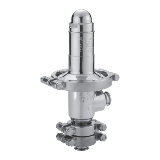
Page 11: Configuration
Configuration Sizes 38, 40 mm ⑰ ⑧ ⑯ ⑮ Enlarged view: A ⑤ ⑫ ⑦ ⑲ ⑪ ⑬ ⑳ ⑩ ㉒ ⑱ ⑥ ㉑ ㉛ ㉚ ③ ④ ⑨ ⑭ Sizes 15, 20 mm Size 25 mm ① ② ㉚ ㉚... - Page 12 Part Name Body ✔ Valve ✔ Diaphragm ✔ Protective Sheet Spring Housing Upper Diaphragm Retainer Coil Spring Lower Diaphragm Retainer Spacer Spring Washer Locknut Plain Washer ✔ ✔ ✔ Retainer Gasket Spring Retainer Locknut Adjustment Screw ✔ Valve Guide ✔ ✔...
-
Page 13: Installation
Installation Caution Install properly and DO NOT use this product outside the recommended operating pressure, temperature and other specification ranges. Improper use may result in such hazards as damage to the product or malfunctions that may lead to serious accidents. Local regulations may restrict the use of this product to below the conditions quoted. - Page 14 4. Piping support Install the product, paying attention to avoid excessive load, bending and vibration. Support the inlet and outlet pipes securely. 5. Maintenance space Leave sufficient space for maintenance, inspection and repair. 6. Piping size/diffuser If it is expected that the secondary steam flow velocity will be more than 30 m/s (100 ft/s), install a diffuser in order to keep the flow velocity below 30 m/s (100 ft/s).
- Page 15 7. Two-stage pressure reduction Employ two-stage pressure reduction if the required reduction is not possible due to product operating range limitations (when it is not possible to reduce to the desired pressure using a single pressure reducing valve). Bypass Valve Bypass Valve Pressure Gauge...
-
Page 16: Adjustment
Adjustment To avoid problems such as water hammer and to protect steam-using equipment, the product should be correctly adjusted. It is necessary to blow down all pipe lines thoroughly. The blowdown is especially important if the line is new or has been shut down for a long period of time. Take particular care to ensure that matter such as condensate and dirt does not remain inside the equipment. -
Page 17: Maintenance
Maintenance Caution Take measures to prevent people from coming into direct contact with product outlets. Failure to do so may result in burns or other injury from the discharge of fluids. Be sure to use only the recommended components when repairing the product, and NEVER attempt to modify the product in any way. -
Page 18: Disassembly
Disassembly Caution When disassembling or removing the product, wait until the internal pressure equals atmospheric pressure and the surface of the product has cooled to room temperature. Disassembling or removing the product when it is hot or under pressure may lead to discharge of fluids, causing burns, other injuries or damage. - Page 19 Disassembling the adjustment section Loosen the cap and the locknut first. Loosen the adjustment screw completely and remove the body clamp. Locknut Spring Housing Adjustment Screw Spring Washer Body Clamp Nut Body Clamp Body Clamp Bolt After removing the spring housing, remove the adjustment screw, spring retainer, and coil spring.
- Page 20 Disassembling the Diaphragm Section Hold the valve in place with an adjustable wrench across the flats on the upper part of the valve and use another wrench to remove the locknut. After removing the locknut, remove the plain washer, the upper diaphragm retainer and the diaphragm. Disassembling the Valve Section Remove the inlet clamp(s) holding the body, valve guide and adapter (for sizes 15 to 20 mm in) only).
- Page 21 Cleaning After inspection and removal of any abnormality, clean and reassemble the parts. The following parts will require cleaning before reassembly: Diaphragm, Protective Sheet, Valve, Valve Guide, Retainer Gasket, Body, Lower Diaphragm Retainer, Adapter (for sizes 15 to 20 mm ( in) only) Note Avoid using solvent to clean these parts as it may accelerate deterioration of the diaphragm,...
- Page 22 Exploded view Sizes 15, 20 mm Sizes 25, 38, 40 mm Option: Sizes 15, 20 mm Part Name Part Name Body Adjustment Screw Valve Valve Guide Diaphragm Inlet Clamp Gasket Protective Sheet Snap Ring Spring Housing Slide Bearing IUpper Diaphragm Retainer Body Clamp Coil Spring Body Clamp Bolt...
-
Page 23: Reassembly
Reassembly Reassemble the unit using the same procedure as used for disassembly; but in reverse order. In addition, observe the following precautions: 1. The diaphragm and the protective sheet also perform the role of gaskets and may be re-used if free from cracks, deterioration or deformation. If any abnormalities are found, these parts need to be replaced. -
Page 24: Troubleshooting
Troubleshooting Caution When disassembling or removing the product, wait until the internal pressure equals atmospheric pressure and the surface of the product has cooled to room temperature. Disassembling or removing the product when it is hot or under pressure may lead to discharge of fluids, causing burns, other injuries or damage. - Page 25 Problem Symptom Cause Remedy Adjustment is difficult, and The flow rate is too low Check the flow rate; check secondary set pressure varies the model selection, pressure replace with a more cannot be suitable unit if necessary adjusted or increases Pressure fluctuation at the Check the primary abnormally...
- Page 26 Contact TLV for model selection and replacement. Note When replacing parts with new, use the parts list for reference and replace with parts from the maintenance kit, repair kit, etc. (Please note that replacement parts are only available in...
-
Page 27: Tlv Express Limited Warranty
TLV; or 4. disasters or forces of nature or Acts of God; or 5. abuse, abnormal use, accidents or any other cause beyond the control of TLV, TII or TLV group companies; or 6. improper storage, maintenance or repair; or 7. - Page 28 HEREBY, INCLUDING THE IMPLIED WARRANTIES OF MERCHANTABILITY AND FITNESS FOR A PARTICULAR PURPOSE, DO NOT COVER, AND NEITHER TLV, TII NOR ITS TLV GROUP COMPANIES WILL IN ANY EVENT BE LIABLE FOR, INCIDENTAL OR CONSEQUENTIAL DAMAGES, INCLUDING, BUT NOT LIMITED TO LOST PROFITS, THE COST OF DISASSEMBLY AND SHIPMENT OF THE DEFECTIVE PRODUCT, INJURY TO OTHER PROPERTY, DAMAGE TO BUYER’S OR THE FIRST...
-
Page 29: Service
Service For Service or Technical Assistance: Contact your TLV representative or your regional TLV office. In Europe: Tel: [49]-(0)7263-9150-0 Daimler-Benz-Straße 16-18, 74915 Waibstadt, Germany Tel: [44]-(0)1242-227223 Units 7 & 8, Furlong Business Park, Bishops Cleeve, Gloucestershire GL52 8TW, U.K. Tel:...
Need help?
Do you have a question about the DR8-3P and is the answer not in the manual?
Questions and answers