Table of Contents
Advertisement
Available languages
Available languages
Quick Links
INSTRUCTION MANUAL
Keep this manual in a safe place for future reference
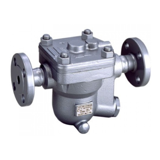
FREE FLOAT TYPE STEAM TRAPS JH-B SERIES
EINBAU- UND BETRIEBSANLEITUNG
Gebrauchsanleitung leicht zugänglich aufbewahren
FREISCHWIMMER KONDENSATABLEITER JH-B SERIE
MANUEL D UTILISATION
Conserver ce manuel dans un endroit facile d'accès
ODWADNIACZE Z PŁYWAKIEM SWOBODNY SERIA JH-B
JH5RL-B
JH5RH-B
JH3-B
JH7RL-B
JH7RM-B
JH7RH-B
JH7.2R-B
JH8R-B
JH7.5R-B
Copyright (C) 2016 by TLV CO., LTD. All rights reserved.
Advertisement
Table of Contents

Subscribe to Our Youtube Channel
Related Manuals for TLV JH-B series


Summary of Contents for TLV JH-B series
- Page 1 FREISCHWIMMER KONDENSATABLEITER JH-B SERIE MANUEL D UTILISATION Conserver ce manuel dans un endroit facile d’accès ODWADNIACZE Z PŁYWAKIEM SWOBODNY SERIA JH-B JH5RL-B JH5RH-B JH3-B JH7RL-B JH7RM-B JH7RH-B JH7.2R-B JH8R-B JH7.5R-B Copyright (C) 2016 by TLV CO., LTD. All rights reserved.
- Page 2 Before beginning installation or maintenance, please read this manual to ensure correct use of the product. Keep the manual in a safe place for future reference. The inline repairable JH-B series steam traps with thermostatic bimetal air vent are suitable for a wide range of applications with small-to-large capacities and pressures up to 10 MPaG (1500 psig), such as all kinds of heat exchangers, process heaters and coils.
- Page 3 • The three types of cautionary items above are very important for safety; be sure to observe all of them, as they relate to installation, use, maintenance, and repair. Furthermore, TLV accepts no responsibility for any accidents or damage occurring as a result of failure to observe these precautions.
- Page 4 • Diese drei Warnzeichen sind wichtig für Ihre Sicherheit. Sie müssen unbedingt beachtet werden, um den sicheren Gebrauch des Produktes zu gewährleisten und Einbau, Wartung und Reparatur ohne Unfälle oder Schäden durchführen zu können. TLV haftet nicht für Unfälle oder Schäden, die durch Nichtbeachtung dieser Sicherheitshinweise entstehen.
- Page 5 • Trzy typy oznaczeń są bardzo ważne dla bezpieczeństwa i należy pamiętać aby zapoznać się z nimi, gdyż dotyczą instalacji, stosowania, obsługi i naprawy. Firma TLV nie odpowiada za jakiekolwiek wypadki i uszkodzenia wynikające z braku stosowania się do tych oznaczeń.
- Page 6 2. Configuration Aufbau Konfiguracja JH5RL-B JH3-B JH5RH-B !0 !1 !6 !7 @0 @1 @2 !4 ! 3 !0 w !2 !1 !6 @0 @1 @2 !3 !5 !4 @6 @ 7 t r u y tr u y JH7RL-B JH7RM-B JH7.2R-B !0 ! 2 @0 @1 @ 2 !9...
-
Page 7: Table Of Contents
Description Description Description Body Cover Gasket Snap Ring Cover Connector Drain Plug Gasket* Float Connector Gasket Drain Plug* Orifice Snap Ring Orifice Locknut Orifice Gasket Air Vent Case Outlet Cover Bolt Orifice Plug or Outlet Cover Bimetal Plate Outlet Cover Nut Plug or Outlet Cover Gasket Air Vent Screen Screen Holder Retainer... - Page 8 3. Specifications Technische Daten Specyfikacja Refer to the product nameplate for detailed specifications. Die technischen Daten stehen auf dem Typenschild. Odnosi się do informacji zawartych na tabliczce znamionowej danego urządzenia A Model B Nominal Diameter Größe/DN Średnica przyłącza/DN C Maximum Allowable Pressure* Maximal zulässiger Druck* Maksymalne dopuszczalne ciśnienie* D Maximum Allowable Temperature* TMA...
-
Page 9: Body
4. Proper Installation • Installation, inspection, maintenance, repairs, disassembly, adjustment CAUTION and valve opening/closing should be carried out only by trained maintenance personnel. • Use the eyebolts for removing the cover only; DO NOT use the eyebolts for hoisting the product. •... -
Page 10: Cover(
Check to make sure that the pipes connected to the trap have been installed properly. 1. Is the pipe diameter suitable? 2. Has the trap been installed within the allowable inclination and with the arrow on the body pointing in the direction of flow? 3. -
Page 11: Float
Disassembly/Reassembly (to reassemble, follow procedures in reverse) JH7RL-B JH3-B JH5RL-B During Disassembly During Reassembly Part & No. JH7RM-B JH7RH-B JH7.5R-B JH8R-B JH5RH-B JH7.2R-B Coat threads with anti-seize and Drain Plug 27 Use a wrench to remove tighten to the proper torque Remove gasket and clean Replace with a new gasket, coat Drain Plug Gasket 26... -
Page 12: Orifice
NOTES for JH7RH-B: Special Points Pertaining to Orifice and Orifice Gasket Reassembly Follow the steps below when inserting the orifice into the body in order to ensure that the gasket does not fall off and is inserted correctly without protruding from the groove. 1. - Page 13 Instructions for Plug / Holder Disassembly and Reassembly The seal on the threaded plugs/holders found on TLV products is formed by a flat metal gasket. There are various installation orientations for the gaskets, such as horizontal, diagonal and downward, and the gasket may be pinched in the thread recesses during assembly.
-
Page 14: Orifice Gasket
(When conducting a visual inspection, flash steam is sometimes mistaken for steam leakage. For this reason, the use of a steam trap diagnostic instrument such as TLV TrapMan is highly recommended.) Flash Steam... -
Page 15: Screen
9. Troubleshooting If the expected performance is unachievable after installation of the steam trap, read chapters 4 and 5 again and check the following points for appropriate corrective measures. Remedy Problem Cause Float is damaged or filled with condensate Replace the float No condensate is discharged Orifice, screen or piping are clogged with rust or... -
Page 16: Gehäusedeckel
4. Einbauhinweise • Einbau und Ausbau, Inspektion, Wartungs- und Reparaturarbeiten, VORSICHT Öffnen/Schließen von Armaturen, Einstellung von Komponenten dürfen nur von geschultem Wartungspersonal vorgenommen werden. • Die Ringschrauben nur zum Abheben des Gehäusedeckels benutzen, NICHT zum Heben des gesamten Produkts. • In sicherer Enfernung von Auslassöffnungen aufhalten und andere Personen warnen, sich fern zu halten. -
Page 17: Schwimmerkugel
Stellen Sie sicher, dass die Rohrleitungsarbeiten richtig ausgeführt wurden und dass der KA wie beschrieben eingebaut wurde: 1. Ist die Nennweite groß genug? 2. Wurde der KA horizontal, bzw. innerhalb der Schräglagentoleranz und mit dem Pfeil in Durchflussrichtung eingebaut? 3. Ist genügend Platz für Wartungsarbeiten vorhanden? 4. -
Page 18: Ventilsitz
Ausbau und Einbau der Teile (Einbau erfolgt in umgekehrter Reihenfolge) JH7RL-B JH5RL-B Ausbau Einbau JH7RM-B Bauteil & Nr. JH3-B JH7RH-B JH7.5R-B JH8R-B JH5RH-B JH7.2R-B Entwässerungs- Gabel- oder Ringschlüssel Gewinde schmieren, Anzugsmoment stopfen 27 verwenden beachten Dichtung entfernen und Dichtung erneuern, mit Schmiermittel Stopfendichtung 26 Dichtflächen reinigen bestreichen... -
Page 19: Ventilsitzdichtung
Hinweise für JH7RH-B: Besondere Punkte zum Zusammenbau von Ventilsitz und Ventilsitzdichtung Setzen Sie den Ventilsitz in folgenden Schritten in das Gehäuse ein, um sicher zu stellen, dass die Ventilsitzdichtung richtig sitzt und nicht aus der Nut hervorsteht: 1. Als erstes den Ventilsitz allein in die vorgesehene Stelle im Gehäuse einsetzen, um zu ermitteln, wie weit er herauszustehen hat. - Page 20 Aus- und Einbau-Anleitung für Entwässerungsstopfen Die Gewindedichtung der Entwässerungsstopfen an TLV-Kondensatableitern besteht aus einem flachen Metallring. Stopfen und Dichtung können in verschiedenen Lagen eingebaut werden - horizontal, diagonal oder nach unten zeigend. Wird der Metallring dabei im Gewinde gequetscht, verliert er seine Funktionstüchtigkeit.
-
Page 21: Stopfendichtung Oder Deckeldichtung
Falls der Kondensatableiter das Kondensat ins Freie abführt, können visuelle Inspektionen einen Hinweis geben, ob sofortige Wartung oder Reparatur notwendig ist. An Kondensatrückführlei- tungen angeschlossene KA können mit geeigneten Messgeräten, z. B. TLV TrapMan oder TLV Pocket TrapMan (innerhalb ihrer Druck- und Temperaturmessbereiche) geprüft werden. -
Page 22: Schmutzsieb
9. Fehlersuche Falls der Kondensatableiter nicht zufriedenstellend arbeitet, lesen Sie nochmals Kapitel 4 und 5. Gehen Sie dann die nachfolgende Fehlerliste durch, um den Fehler zu orten und zu korrigieren. Symptom Ursachen Gegenmaßnahmen Schwimmerkugel ist beschädigt, oder voll Wasser Schwimmerkugel ersetzen Kondensat läuft nicht ab (blockiert), Ventilsitz, Schmutzsieb oder Rohrleitungen sind... - Page 23 4. Właściwa instalacja • Instalacja, inspekcja, obsługa, naprawa, montaż i demon-taż, nastawa UWAGA oraz uruchamianie odwadniacza może być przeprowadzana tylko przez odpowiednio przeszkolony i upoważniony personel. • Nie wolno dopuszczać do kontaktu ludzi z czynnikiem wylotowym z odwadniacza. • Używać w instalacjach, w których nie ma zagrożenia uderzeniami hydraulicznymi.
- Page 24 Sprawdź aby upewnić się że odwadniacz został prawidłowo zamontowany 1. Czy jest odpowiednia średnica? 2. Czy strzałka na korpusie jest zgodna z kierunkiem przepływu oraz czy pochylenie odwadniacza mieści się w zaleceniach? 3. Czy wokół odwadniacza znajduje się odpowiednia przestrzeń dla jego obsługi i naprawy? 4.
-
Page 25: Pokrywa
Demontaż / Montaż (dla montażu postępować w odwrotnej kolejności) JH7RL-B JH5RL-B Podczas demontażu Podczas montażu Numer części JH7RM-B JH3-B JH7RH-B JH7.5R-B JH8R-B JH5RH-B JH7.2R-B Pokryć gwinty pastą do gwintów Korek nr 27 Użyć klucza i zdjąć Dokręcić z zalecanym momentem Uszczelka korka Zdjąć... -
Page 26: Kryza
Uwagi dla JH7RH-B: Specjalne punkty dotyczące kryzy i uszczelki kryzy Należy zastosować się do poniższych punktów podczas zakładania kryzy do korpusu aby upewnić się że uszczelka nie wypadnie i jest włożona prawidłowo nie kolidując z rowkiem 1. Najpierw, włożyć kryzę bez uszczelki do gniazda kryzy w korpusie , po to żeby zorientować się ile będzie wystawać. - Page 27 Instrukcja montażu/demontażu korka Uszczelnienie gwintu korka jest realizowane w produktach TLV na płaskiej powierzchni i metalowej uszczelce. Występują różne orientacje dla tych uszczelek , poziome , pionowe , skośne i uszczelka może być wciągnięta do gwintu podczas montażu. Instrukcja montażu i demontażu| Zdjąć...
-
Page 28: Uszczelka Pokrywy
Jeżeli odwadniacz jest podłączony do zamkniętego układu kondensatu, można wówczas użyć specjalistycznego urządzenia diagnostycznego firmy TLV typu TrapMan lub PT1. Normalna Kondensat jest odprowadzany stale, może wystąpić para wtórna słyszalna na wylocie. - Page 29 9. Wykrywanie usterek Jeżeli odwadniacz nie pracuje w satysfakcjonujący sposób należy przede wszystkim sprawdzić rozdziały 4 oraz 5 niniejszej instrukcji, a potem przejść do punktów poniżej. Problem Przyczyna Rozwiązanie Brak Pływak uszkodzony lub Wymienić pływak odprowadzania wypełniony kondensatem kondensatu Zawór odwadniacza, siatka filtra lub Oczyścić...
- Page 30 10. Product Warranty 1) Warranty Period: one year after product delivery. 2) TLV CO., LTD. warrants this product to the original purchaser to be free from defective materials and workmanship. Under this warranty, the product will be repaired or replaced at our option, without charge for parts or labor.
- Page 31 For Service or Technical Assistance: Contact your representative or your regional office. Für Reparatur und Wartung: Wenden Sie sich bitte an Ihre Vertretung oder an eine der Niederlassungen. Pour tout service ou assistance technique: Contactez votre agent ou votre bureau régional USA and Canada: Te l : [1]-704-597-9070 USA und Kanada:...
- Page 32 Manufacturer: Tel: [81]-(0)79-422-1122 Hersteller: 881 Nagasuna, Noguchi, Kakogawa, Fax: [81]-(0)79-422-0112 Fabricant: Hyogo 675-8511, Japan Printed on recycled paper. Auf Recycling-Papier gedruckt. Imprimé sur du papier recyclé. Rev. 4/2016 (M)
Need help?
Do you have a question about the JH-B series and is the answer not in the manual?
Questions and answers