Table of Contents
Advertisement
Quick Links
Advertisement
Table of Contents

Related Manuals for TLV COSR-3


Summary of Contents for TLV COSR-3
- Page 1 ISO 9001 ISO14001 Manufacturer Kakogawa, Japan is approved by LRQA Ltd. to ISO 9001/14001 Instruction Manual Pressure Reducing Valve for Steam Featured Models: COSR-3/COSR-16/COSR-21/COSR-16HT 172-65174M-13 Publication date 20 February 2024 Copyright © 2024 TLV CO., LTD.
-
Page 2: Table Of Contents
Specifications ........................... 6 Correct usage of the product ....................7 Configuration ..........................9 Installation ..........................15 Adjustment ..........................19 Maintenance ........................... 20 Disassembly ........................... 21 Reassembly ..........................27 Troubleshooting ........................29 TLV EXPRESS LIMITED WARRANTY ................... 32 Service ........................... 34... -
Page 3: Introduction
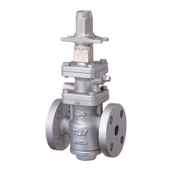
The TLV pressure reducing valve for steam, model COSR provides a more stable secondary pressure than conventional reducing valves. The COSR is designed for long service life, with all major components made of stainless steel for superior durability. -
Page 4: Safety Considerations
• The three types of cautionary items above are very important for safety: be sure to observe all of them as they relate to installation, use, maintenance and repair. Furthermore, TLV accepts no responsibility for any accidents or damage occurring as a result of failure to observe these precautions. - Page 5 Caution Do not use excessive force when connecting threaded pipes to the product. Over-tightening may cause breakage leading to fluid discharge, which may cause burns or other injury. Caution Use only under conditions in which no freeze-up will occur. Freezing may damage the product, leading to fluid discharge, which may cause burns or other injury.
-
Page 6: Specifications
Production Lot No. Primary Pressure Range Valve No. is displayed for products with options. This item is omitted from the nameplate when there are no options. Acceptable Operating Range Model COSR-3 COSR-16 COSR-16HT COSR-21 Primary Pressure 0.1 to 0.3 MPaG 0.2 to 1.6 MPaG... -
Page 7: Correct Usage Of The Product
Correct usage of the product Caution Install properly and DO NOT use this product outside the recommended operating pressure, temperature and other specification ranges. Improper use may result in such hazards as damage to the product or malfunctions that may lead to serious accidents. Local regulations may restrict the use of this product to below the conditions quoted. - Page 8 Recommended straight pipe runs If the product is installed either directly before or after an elbow or control valve, unevenness in flow may result in chattering and unstable pressure. To ensure a stable flow, it is recommended that the product be installed on straight runs of piping, as illustrated below. (d = pipe diameter) Inlet (primary) side •...
-
Page 9: Configuration
Configuration COSR-3/COSR-16 Sizes 15 to 25 mm Part Name Main Body Cover Plug ✔ Main Valve Seat ✔ Main Valve ✔ Main Valve Holder ✔ Piston ✔ Cylinder Pilot Body ✔ Pilot Valve ✔ Pilot Valve Seat Diaphragm ✔ Pilot Screen... - Page 10 Main Valve, C = Repair Kit for Piston, D = Repair Kit for Piston Rings, E = Repair Kit for Pilot Valve Size 15 mm not available for COSR-3 COSR-3 Sizes 32 to 50 mm/COSR-16 Sizes 32 to 50 mm/COSR-21 Sizes 15 to 50 mm Part Name...
- Page 11 Replacement parts are available only in the following kits: A = Maintenance Kit, B = Repair Kit for Main Valve, C = Repair Kit for Piston, D = Repair Kit for Piston Rings, E = Repair Kit for Pilot Valve Size 15 mm not available for COSR-3 Note Contact TLV for COSR-21 replacement parts.
- Page 12 Replacement parts are available only in the following kits: A = Maintenance Kit, B = Repair Kit for Main Valve, C = Repair Kit for Piston, D = Repair Kit for Piston Rings, E = Repair Kit for Pilot Valve Note Contact TLV for COSR-21 replacement parts.
- Page 13 COSR-16HT Sizes 65 to 100 mm Part Name Main Body Cover ✔ Main Valve Seat ✔ Main Valve ✔ Main Valve Holder ✔ Piston ✔ Cylinder Pilot Body ✔ Pilot Valve ✔ Pilot Valve Seat Diaphragm ✔ Pilot Screen Pilot Screen Holder Diaphragm Support Coil Spring Spring Housing...
- Page 14 Part Name ✔ ✔ ✔ Cylinder Gasket ✔ ✔ Plug Gasket ✔ ✔ Piston Ring ✔ ✔ Tension Ring ✔ ✔ Seal Ring Pilot Valve Cover ✔ Main Valve Spring ✔ Pilot Valve Spring Silencer Replacement parts are available only in the following kits: A = Maintenance Kit, B = Repair Kit for Main Valve, C = Repair Kit for Piston, D = Repair Kit for Piston Rings, E = Repair Kit for Pilot Valve...
-
Page 15: Installation
Installation Caution Install properly and DO NOT use this product outside the recommended operating pressure, temperature and other specification ranges. Improper use may result in such hazards as damage to the product or malfunctions that may lead to serious accidents. Local regulations may restrict the use of this product to below the conditions quoted. - Page 16 Installing a spacer If spacing adjustment is necessary to accommodate installation, install a spacer on the outlet flange. The spacer should consist of a spacer, gaskets, bolts and nuts. Fit gaskets to both sides of the spacer between the product outlet and the pipe flange. Fasten with bolts and nuts. Piping support Install the product, paying attention to avoid excessive load, bending and vibration.
- Page 17 Two-stage pressure reduction Two-stage pressure reduction should be performed whenever the pressure cannot be reduced to the desired level with a product due to operating range limitations. Bypass Bypass Valve Valve Safety Valve Pressure (Relief Valve) Gauge Pressure Pressure Gauge Gauge Shut-off Shut-off...
- Page 18 Pilot Body Plug Rc(PT) Plug PF (sizes 65 to 100 mm for COSR-16HT) Blind Pin Main Body Connecting Tube Pilot Body Bolt Loosen and remove the pilot body bolt (F) or the pilot cover (65 to 150 mm) and remove the pilot body (A).
-
Page 19: Adjustment
Adjustment The product should be properly adjusted for protection of the equipment against water hammer. It is necessary to blow down all pipe lines thoroughly. The blowdown is especially important if the line is new or has been shut down for a long period of time. Take particular care to ensure that matter such as condensate and dirt does not remain inside the equipment. -
Page 20: Maintenance
Maintenance Caution Take measures to prevent people from coming into direct contact with product outlets. Failure to do so may result in burns or other injury from the discharge of fluids. When disassembling or removing the product, wait until the internal pressure equals atmospheric pressure and the surface of the product has cooled to room temperature. -
Page 21: Disassembly
Disassembly Caution Use hoisting equipment for heavy objects (weighing approximately 20 kg (44 lb) or more). Failure to do so may result in back strain or other injury if the object should fall. Caution When disassembling or removing the product, wait until the internal pressure equals atmospheric pressure and the surface of the product has cooled to room temperature. - Page 22 Disassembling the adjustment section Loosen the adjustment screw completely and remove the bolts. Having removed the spring housing, you will see the diaphragm support, coil spring and spring guide. Important Check for seizure or any damaged screw threads. Sizes 15 to 150 mm Adjustment Screw Spanner Cap Ball...
- Page 23 Sizes 65 to 150 mm Diaphragm Pilot Valve Seat (with Gasket) Sensing Line Plug Pilot Body Upper Pilot Body Gasket Pilot Bolt Pilot Valve Notch Pilot Screen Pilot Valve Spring Connecting Pilot Screen Holder Tubes (with Gasket) Pilot Cover Bolt Pilot Cover Disassembling the piston section Remove the pilot body after loosening and removing the bolts (stud bolts).
- Page 24 At start-up following shut-down for a long period, always blow down the piston section of the body through the plug (option). COSR-3: Sizes 20 and 25 mm/COSR-16 and COSR-16HT: Sizes15 to 25 mm Main Valve Seat Gasket Main Valve Seat...
- Page 25 COSR-16: Sizes 65 to 150 mm/COSR-16HT and COSR-21: 65 to 100 mm Main Valve Seat Gasket Main Valve Seat Hex Bolt Main Valve Main Valve Holder Cover Cover Gasket Main Body Main Valve Spring Cover Bolt Sleeve (fixed) Cleaning After inspection and removal of any abnormality, clean and reassemble the parts. The following parts will require cleaning before reassembly: Cover Plug/Cover, Pilot Screen, Main Valve Seat, Main Valve, Main Valve Holder, Piston, Piston Ring, Cylinder, Pilot Valve, Pilot Valve Seat, Adjustment Screw...
- Page 26 Exploded View 32 to 50 mm 65 to 150 mm Adjustment section Pilot section 15 to 25 mm Piston section Main Valve section...
-
Page 27: Reassembly
Reassembly Reassemble the unit using the same procedure as used for disassembly; but in reverse order. In addition, observe the following precautions. The PTFE gaskets may be re-used if free from fault, crushing or deformation. Apply anti-seize to the threaded portion of screws and bolts, the spring retainer, ball and adjustment screw. - Page 28 Main Valve Seat 15, 20 32, 40 Bolts (Main Valve Seat) 65, 80 100, 125 Cover Plug 15 to 20 (COSR-3, COSR-16) Cover Bolt 15 to 25 16 or 17 32, 40 16 or 17 50 to 80 18 or 19...
-
Page 29: Troubleshooting
Troubleshooting Caution When disassembling or removing the product, wait until the internal pressure equals atmospheric pressure and the surface of the product has cooled to room temperature. Disassembling or removing the product when it is hot or under pressure may lead to discharge of fluids, causing burns, other injuries or damage. - Page 30 Problem Symptom Cause Remedy The secondary Adjustment is difficult, The pilot screen is Clean pressure cannot and set pressure varies clogged be adjusted or There is insufficient Check the flow, replace increases steam flow the COSR if necessary abnormally The piston is clogged Clean with dirt Check the piston ring...
- Page 31 Note When replacing parts with new for the COSR-3 and COSR-16, use the parts list for reference, and replace with parts from the kits shown there. Please note that replacement parts for the COSR-3 and COSR-16 are only available as part of a replacement parts kit.
-
Page 32: Tlv Express Limited Warranty
Subject to the limitations set forth below, TLV CO., LTD., a Japanese corporation ("TLV"), warrants that products which are sold by it, TLV International Inc. ("TII") or one of its group companies excluding TLV Corporation (a corporation of the United States of America), (hereinafter the "Products") are designed and manufactured by TLV, conform to the... - Page 33 HEREBY, INCLUDING THE IMPLIED WARRANTIES OF MERCHANTABILITY AND FITNESS FOR A PARTICULAR PURPOSE, DO NOT COVER, AND NEITHER TLV, TII NOR ITS TLV GROUP COMPANIES WILL IN ANY EVENT BE LIABLE FOR, INCIDENTAL OR CONSEQUENTIAL DAMAGES, INCLUDING, BUT NOT LIMITED TO LOST PROFITS, THE COST OF DISASSEMBLY AND SHIPMENT OF THE DEFECTIVE PRODUCT, INJURY TO OTHER PROPERTY, DAMAGE TO BUYER’S OR THE FIRST...
-
Page 34: Service
Service For Service or Technical Assistance: Contact your TLV representative or your regional TLV office. In Europe: Tel: [49]-(0)7263-9150-0 Daimler-Benz-Straße 16-18, 74915 Waibstadt, Germany Tel: [44]-(0)1242-227223 Units 7 & 8, Furlong Business Park, Bishops Cleeve, Gloucestershire GL52 8TW, U.K. Tel:...
Need help?
Do you have a question about the COSR-3 and is the answer not in the manual?
Questions and answers