Advertisement
Quick Links
ISO 9001
ISO14001
Manufacturer
Kakogawa, Japan
is approved by LRQA Ltd. to ISO 9001/14001
Instruction Manual
Free Float Steam Trap
Featured Models: FS1NL/FS1NH
Optional Models: FS1NL-TZ/FS1NH-TZ
Trap Units: S1NL/S1NH (For Connector Body F46)
Optional Models: S1NL-TZ/S1NH-TZ
172-65635M-01
Publication date 31 October 2024
Copyright © 2024 TLV CO., LTD.
Advertisement

Related Manuals for TLV QuickTrap FS1NL


Summary of Contents for TLV QuickTrap FS1NL
- Page 1 LRQA Ltd. to ISO 9001/14001 Instruction Manual Free Float Steam Trap Featured Models: FS1NL/FS1NH Optional Models: FS1NL-TZ/FS1NH-TZ Trap Units: S1NL/S1NH (For Connector Body F46) Optional Models: S1NL-TZ/S1NH-TZ 172-65635M-01 Publication date 31 October 2024 Copyright © 2024 TLV CO., LTD.
- Page 2 Specifications ........................... 8 Compatibility ..........................9 Configuration .......................... 10 Installation ..........................11 Maintenance ........................... 13 Disassembly/Reassembly ...................... 14 Instructions for Plug/Holder Disassembly and Reassembly ........... 18 Troubleshooting ........................19 TLV EXPRESS LIMITED WARRANTY ................... 20 Service ........................... 22 Options ........................... 23...
- Page 3 Introduction Thank you for purchasing the TLV free float steam trap. This product has been thoroughly inspected before being shipped from the factory. When the product is delivered, before doing anything else, check the specifications and external appearance to make sure nothing is out of the ordinary. Also be sure to read this manual carefully before use and follow the instructions to be sure of using the product properly.
- Page 4 • The three types of cautionary items above are very important for safety: be sure to observe all of them as they relate to installation, use, maintenance and repair. Furthermore, TLV accepts no responsibility for any accidents or damage occurring as a result of failure to observe these precautions.
- Page 5 Caution Be sure to use only the recommended components when repairing the product, and NEVER attempt to modify the product in any way. Failure to observe these precautions may result in damage to the product and burns or other injury due to malfunction or the discharge of fluids. Caution Use only under conditions in which no freeze-up will occur.
- Page 6 Have isolation valves been installed at the inlet and outlet? If the outlet is subject to back pressure, has a check valve (TLV-CK) been installed? Is the inlet pipe as short as possible, with as few bends as possible, and installed so the...
- Page 7 Operation Principles of air and condensate discharge: Air and Cold Condensate Discharge at Startup At startup, before steam is supplied, the system is cold and the air vent strip (bimetal) is contracted, holding the float off the orifice. This allows for the rapid discharge of air and cold condensate through the valve when steam is first supplied to the system.
- Page 8 Specifications Caution Install properly and DO NOT use this product outside the recommended operating pressure, temperature and other specification ranges. Improper use may result in such hazards as damage to the product or malfunctions that may lead to serious accidents. Local regulations may restrict the use of this product to below the conditions quoted.
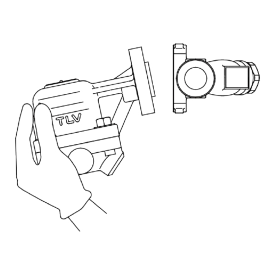
- Page 9 Compatibility • Trap units S1NL/S1NH are compatible with TLV F46 and F32 connector units, trap stations (V1/V2/V1P/V2P Series) and QuickStation QS10/QS18. The connector unit name is indicated on the connector body.
- Page 10 Configuration ① ⑥ ⑫ ⑰ ⑯ ㉔ ㉓ ⑱ ⑳ ⑲ ⑧ ⑭ ⑮ ㉑ ㉒ ⑬ ⑤ ② ⑦ ⑨ ③ ⑪ ⑩ ④ Part Name ✓ Trap Body ✓ Cover ✓ ✓ Float ✓ ✓ Orifice ✓ ✓ ✓...
- Page 11 Installation Caution Install properly and DO NOT use this product outside the recommended operating pressure, temperature and other specification ranges. Improper use may result in such hazards as damage to the product or malfunctions that may lead to serious accidents. Local regulations may restrict the use of this product to below the conditions quoted.
- Page 12 Installation Examples Horizontal Piping Incorrect Correct Connector Flange is not in the vertical Nameplate is not facing upwards plane a= Name Plate, b= Connector Flange, c= Ground Vertical Piping Incorrect Correct Nameplate is not facing upwards a= Name Plate, b= Connector Flange, c= Ground Note Screwed Connection When products with screwed connections are installed on horizontal piping, there is a danger that...
- Page 13 Periodically (at least biannually) the operation should also be checked by using diagnostic equipment such as a stethoscope, thermometer, TLV Pocket TrapMan or TLV TrapMan. If the product should fail, it may cause damage to piping and equipment, resulting in faulty or low quality products or losses due to steam leakage.
- Page 14 Disassembly/Reassembly Warning NEVER apply direct heat to the float. The float may explode due to increased internal pressure, causing accidents leading to serious injury or damage to property and equipment. Caution When disassembling or removing the product, wait until the internal pressure equals atmospheric pressure and the surface of the product has cooled to room temperature.
- Page 15 Detaching/Reattaching the Cover and Float Part Name & No. During Disassembly During Reassembly Cover Bolt 8 Remove with a socket wrench Consult the table of tightening torques and tighten to the proper torque Cover 2 Remove, being careful not to damage Make sure there are no pieces of the old the float, which may fall out when the gasket on the sealing surfaces, align the...
- Page 16 Table of Tightening Torques Distance Across Part Name & No. Trque N·m Flats mm Orifice 4 Cover Bolt 8 Connector Bolt 18 Screw 10, Spring Washer 11 Screen Holder 22 (when F46 is used) Screen Holder 22 Flanged 15 to 25 mm (when F32 is used) Screwed 15, 20 mm...
- Page 17 Exploded View 10, 11 Part Name Part Name Trap Body Connector Cover Outer Connector Gasket Float Inner Connector Gasket Orifice Snap Ring Orifice Gasket Connector Flange Trap Screen Connector Bolt Cover Gasket Connector Body Cover Bolt Screen Air Vent Strip (bimetal) Screen Holder Gasket Screw Screen Holder...
- Page 18 Instructions for Plug/Holder Disassembly and Reassembly The seal on the threaded plugs/holders found on TLV products is formed by a flat metal gasket. There are various installation orientations for the gaskets, such as horizontal, diagonal and downward, and the gasket may be pinched in the thread recesses during assembly.
- Page 19 Troubleshooting Caution When disassembling or removing the product, wait until the internal pressure equals atmospheric pressure and the surface of the product has cooled to room temperature. Disassembling or removing the product when it is hot or under pressure may lead to discharge of fluids, causing burns, other injuries or damage.
- Page 20 Subject to the limitations set forth below, TLV CO., LTD., a Japanese corporation ("TLV"), warrants that products which are sold by it, TLV International Inc. ("TII") or one of its group companies excluding TLV Corporation (a corporation of the United States of America), (hereinafter the "Products") are designed and manufactured by TLV, conform to the...
- Page 21 HEREBY, INCLUDING THE IMPLIED WARRANTIES OF MERCHANTABILITY AND FITNESS FOR A PARTICULAR PURPOSE, DO NOT COVER, AND NEITHER TLV, TII NOR ITS TLV GROUP COMPANIES WILL IN ANY EVENT BE LIABLE FOR, INCIDENTAL OR CONSEQUENTIAL DAMAGES, INCLUDING, BUT NOT LIMITED TO LOST PROFITS, THE COST OF DISASSEMBLY AND SHIPMENT OF THE DEFECTIVE PRODUCT, INJURY TO OTHER PROPERTY, DAMAGE TO BUYER’S OR THE FIRST...
- Page 22 Service For Service or Technical Assistance: Contact your TLV representative or your regional TLV office. In Europe: Tel: [49]-(0)7263-9150-0 Daimler-Benz-Straße 16-18, 74915 Waibstadt, Germany Tel: [44]-(0)1242-227223 Units 7 & 8, Furlong Business Park, Bishops Cleeve, Gloucestershire GL52 8TW, U.K. Tel:...
- Page 23 The options shown below are available for this product on request. Please compare with the product you received. Options for Area A (Screen Holder) With Blowdown Valve (TLV BD2) Caution Always wear eye protection and heat-resistant gloves when operating the blowdown valve.
- Page 24 Note Avoid the use of excessive tightening torques, as threaded parts may become damaged. TLV Blowdown Valve: BD2 The BD2 Blowdown Valve, installed in the screen area of the body, uses the trap’s internal pressure to blow any condensate, steam, dirt or scale accumulated around the screen area out to the atmosphere.
- Page 25 6 Gland Retainer Nut These models are not available in all regions. TLV Scale Removal Function: -TZ The -TZ Scale Removal Function, installed in the cover of the trap unit, uses a specially designed rod to remove dirt or scale accumulated in the orifice to prevent/eliminate blockage.
- Page 26 Installation This product is fitted with an orifice scale removal unit that requires a certain amount of maintenance space for this operation. The recommended maintenance space (a = approx. 50 mm), measured from the ground (b) to the product, is shown in the figure to the right. Install flanged connector bodies horizontally only.
- Page 27 Hold the gland case securely in place using a tool such as an adjustable wrench or an open-end wrench and slowly turn the removal rod back to the left until it will turn no further. The scale that had been clogging the orifice opening has now been removed and the trap is restored to normal operation.
Need help?
Do you have a question about the QuickTrap FS1NL and is the answer not in the manual?
Questions and answers