Table of Contents
Advertisement
Quick Links
Download this manual
See also:
Instruction Manual
INSTRUCTION MANUAL
Keep this manual in a safe place for future reference
DIRECT-ACTING PRESSURE REDUCING
VALVE FOR STEAM AND/OR AIR
MODEL DR20/A-DR20
DR20
A-DR20
Manufacturer
881 Nagasuna, Noguchi, Kakogawa, Hyogo 675-8511, Japan
Tel: [81]-(0)79-422-1122 Fax: [81]-(0)79-422-0112
Copyright (C) 2018 by TLV CO., LTD. All rights reserved.
Advertisement
Table of Contents

Subscribe to Our Youtube Channel
Related Manuals for TLV DR20


Summary of Contents for TLV DR20
- Page 1 Keep this manual in a safe place for future reference DIRECT-ACTING PRESSURE REDUCING VALVE FOR STEAM AND/OR AIR MODEL DR20/A-DR20 DR20 A-DR20 Manufacturer 881 Nagasuna, Noguchi, Kakogawa, Hyogo 675-8511, Japan Tel: [81]-(0)79-422-1122 Fax: [81]-(0)79-422-0112 Copyright (C) 2018 by TLV CO., LTD. All rights reserved.
-
Page 2: Safety Considerations
Keep the manual in a safe place for future reference. The DR20 direct-acting pressure reducing valve for steam and air is capable of reducing from primary pressures of between 0.2 and 1.6 MPaG (30 – 230 psig) to secondary pressures between 0.014 and 1.0 MPaG (2 –... -
Page 3: Specifications
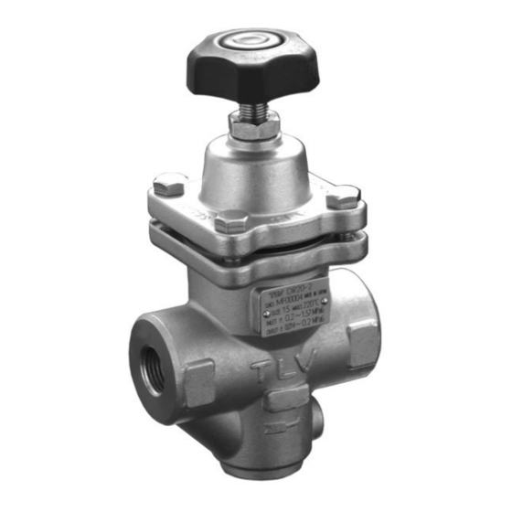
Maximum Operating Primary Pressure Range Temperature Secondary Pressure Adjustable Range Valve No. is displayed for products with options. This item DR20: Steam, Air Applicable is omitted from the nameplate when there are no options. Fluids A-DR20: Air Operating Range DR20-2... - Page 4 3. Configuration For A-DR20: Rubber (standard: fluorine rubber) is used in the seating area. The rubber is inlaid in the main valve. Soft Seat (Fluorine rubber) A-DR20 DR20 Description Description Description Body Cover Bolt Snap Ring Cover Locknut Valve Stem...
-
Page 5: Exploded View
Cannot be removed individually as it is incorporated with the spacer and must be replaced as a set with the spacer. For A-DR20: The rubber is inlaid in the main valve and cannot be removed. The main valve itself must be replaced. -
Page 6: Piping And Installation
5. Piping and Installation • Installation, inspection, maintenance, repairs, disassembly, adjustment and CAUTION valve opening/closing should be carried out only by trained maintenance personnel. • Take measures to prevent people from coming into direct contact with product outlets. • Install for use under conditions in which no freeze-up will occur. •... -
Page 7: Remove Protective Seals
If an on-off valve is required to stop the supply of steam or air to the equipment, install it on the inlet side of the DR20/A-DR20. If a solenoid valve is installed at the outlet of the DR20/A-DR20, it will cause heavy chattering and may lead to damage of the DR20/A-DR20. -
Page 8: Piping Size / Diffuser
5.7 Piping Supports / Maintenance Space Install the Leave sufficient DR20/A-DR20, space for paying attention to maintenance, avoid excessive load, inspection and bending and repair. vibration. Supporting the inlet and outlet pipes securely is recommended. (6″ ) (6″ ) 5.8 Piping Size / Diffuser If the secondary side flow velocity is expected to be more than 30 m/s (100 ft/s), install a diffuser in order to keep the flow velocity below 30 m/s (100 ft/s). - Page 9 Loosen the locknut adjustment handle 4. Slowly, fully open the shut-off valve at the inlet of the DR20/A-DR20. 5. Slightly open the shut-off valve at the outlet of the DR20/A-DR20. 6. Turn the adjustment handle clockwise until the desired outlet pressure is obtained. Wait several minutes.
-
Page 10: Inspection And Maintenance
Gaskets Check for warping or damage Wait for the body to cool before attempting to remove the DR20/A-DR20 from the line. Then remove the DR20/A-DR20 from the piping and secure it in a vise to perform the inspection. 7.1 Disassembling the Adjustment Section... - Page 11 Body Main Valve* * For A-DR20: The rubber is inlaid in the main valve and cannot be removed. The main valve itself must be replaced. 7.4 Cleaning After inspection and removal of any abnormality, clean and reassemble the parts.
-
Page 12: Troubleshooting
This product is shipped after stringent checks and inspection, and should perform its intended function for a long period of time without failure. However, should there be any problem encountered in the operation of the DR20/A-DR20, Consult the troubleshooting guide below. Problem... -
Page 13: Express Limited Warranty
Subject to the limitations set forth below, TLV Corporation, a North Carolina corporation (“TLV”) warrants that products which are sold by it or TLV International, Inc., a Japanese corporation (“TII”), which products (the “Products”) are designed and manufactured by TLV Co., Ltd., a Japanese corporation (“TLVJ”), conform to the specifications published by TLV for the... - Page 14 WARRANTY NOT NEGATED HEREBY, AND ANY IMPLIED WARRANTY NOT NEGATED HEREBY, INCLUDING THE IMPLIED WARRANTIES OF MERCHANTABILITY AND FITNESS FOR A PARTICULAR PURPOSE, DO NOT COVER, AND NEITHER TLV, TII NOR TLVJ WILL IN ANY EVENT BE LIABLE FOR, INCIDENTAL OR CONSEQUENTIAL DAMAGES, INCLUDING, BUT NOT LIMITED TO LOST PROFITS, THE COST OF DISASSEMBLY AND SHIPMENT OF THE DEFECTIVE PRODUCT, INJURY TO OTHER PROPERTY, DAMAGE TO BUYER’S OR THE...
- Page 16 Manufacturer: Tel: [81]-(0)79-422-1122 881 Nagasuna, Noguchi, Kakogawa, Fax: [81]-(0)79-422-0112 Hyogo 675-8511, Japan Printed on recycled paper. PAC-65334-a Rev. 3/2018 (M)
Need help?
Do you have a question about the DR20 and is the answer not in the manual?
Questions and answers