Advertisement
Quick Links
90
°
Angle Spindle
RAS- 101 ・ RAS- 151 E
OPERATION MANUAL
Thank you for purchasing 90 ° Angle Spindle RAS - 101 / RAS - 151 E. This spindle is designed for grinding, small
diameter drilling and milling.
The <E 3000 CONTROLLER / E 2530 Control Unit>, < Brushless Motor> or <Air Motor> and <Air Line Kit > are
rquired to drive this spindle. Read this Operation Manual carefully before use. Also read <E 3000 CONTROLLER /
E 2530 Control Unit>, <Brushless Motor> or <Air Motor> and <Air Line Kit> Operation Manuals.
1 . CAUTIONS FOR HANDLING AND OPERATION
■ Read these warnings and cautions carefully and only use in the manner intended.
■ These warnings and cautions are intended to avoid potential hazards that could result in personal injury or
damage to the device. These are classified as follows in accordance with the seriousness of the risk.
Class
A safety hazard could result in bodily injury or damage to the device if the
WARNING
safety instructions are not properly followed.
A hazard that could result in light or moderate bodily injury or damage
CAUTION
to the device if the safety instructions are not followed.
WARNING
①
This spindle is not a hand tool. It is designed to be used on CNC machines or special purpose
machines.
②
Do not touch the cutting tool while it is running. It is very dangerous.
③
Wear safety glasses, dust mask and use a protective cover around the spindle whenever the
spindle is rotating.
④
Never connect, disconnect or touch the Power Cord Plug and Motor Cord Connector with wet
hands. This may cause an electric shock.
⑤
Never operate or handle the spindle until you have thoroughly read the owner's manual and
safe operation has been confirmed.
1 ) To prevent injuries / damages, check the spindle and cutting tool for proper installation,
before operating the spindle.
2 ) Before disconnecting the spindle, always turn the control power off and turn the compressed
air supply to the Control Unit off. Then it is safe to remove the spindle.
⑥
When installing a spindle to a fixed base, make sure the fixed base is grounded in order to
avoid the risk of an electric shock.
⑦
When installing a tool, tighten the collet chuck correctly and check again the collet chuck and
chuck nut before use. Do not over-tighten the collet chuck. This may cause damage to the spindle.
⑧
Do not use bent, broken, chipped, out of round or sub-standard tools as they may cause
shatter or explode. Tool with fractures or a bent shank will cause injury to the operator. When
using a new tool, rotate it in a low speed and increase speed gradually for safety.
⑨
Do not exceed the maximum recommended allowable tool speed. For your safety, use speeds
below the maximum allowable speed.
⑩
Do not apply excessive force. This may cause tool slippage, tool damage, injury to the operator
or loss of concentricity and precision.
CAUTION
①
Do not ecxeed the maximum allowable motor speed 20,000min
②
Do not drop or hit this spindle, as shock can damage to the internal components.
③
Be sure to clean the collet chuck and chuck nut, the inside of the spindle before replacing the
tool. If ground particles or metal chips stick to the inside of spindle or the collet chuck, damage
to the collet chuck or spindle can occur due to the loss of precision.
④
When cleaning a spindle, stop the motor and remove debris with a soft brush or a cloth. Do not
blow air into the dust proof cover area (refer to section " 3 - 2 Outside view " ) with compressed
air as foreign particles or cutting debris may get into the ball bearing.
⑤
Always clean the tool shank before installing the tool in the spindle.
When sizing the correct collet chuck size to the tool shank diameter, a tolerance of + 0 〜 - 0.01mm
⑥
is strongly recommended. A tool shank within the + 0 〜 - 0.1mm range is mountable, however,
this may cause poor concentricity and or insufficient tool shank gripping force.
⑦
Select suitable products or tools for all applications. Do not exceed the capabilities of the
spindle or tools.
⑧
Carefully direct coolant spray to the tool. Do not spray directly on the spindle body.
⑨
Stop working immediately when abnormal rotation or unusual vibration are observed.
Afterwards, please check the content of section " 10 TROUBLESHOOTING ".
⑩
Always check if the tool, collet chuck or chuck nut are damaged before and after operating.
⑪
If the collet chuck or chuck nut show signs of wear or damage, replace them before a malfunction
or additional damage occurs.
⑫
After installation, repair, initial operation, or long periods of non operation, please refer to
section " 8. BREAK-IN PROCEDURE " detailed in Table 2. When checking the spindle, no
vibration or unusual sound should be observed during rotation.
⑬
Do not disassemble, modify or attempt to repair this spindle. Additional damage will occur
to the internal components. Service must be performed by NSK NAKANISHI or an authorized
service center.
⑭
When using this spindle for mass production, please purchase the another spindle as a spare
in case of an emergency.
2 . FEATURES
① The spindle is capable of working on corners dificult to work or unit for working or unfit for working with straight
type spindle.
② The spindle housing is made from precision ground, hardened, stainless steel (SUS) with an outside diameter
of
22.8mm ( RAS-101 ) or
30mm ( RAS-151E ).
③ Various sizes of collet chucks are available CHK 0.5mm - 6.35mm. Standard collet chuck is CHK - 3.0mm or
CHK - 3.175mm. ( For U.S. market CHK - 3.175mm. )
3 . SPECIFICATIONS AND DIMENSIONS
3 - 1 Specification
Model
For Air Motor
2,870min
Maximum rotating
speed at the tool
For Brushless Motor
7,490min
For Air Motor
7,650min
Maximun Motor
Rotation Speed
For Brushless Motor
20,000min
AM - 300R / L, AM - 300RA / LA
For Air Motor
AM - 310R / L, AM - 310RA / LA
Applicable Motor
EM25 - 5000 - 4M / 5M / 8M
For Brushless Motor
EM25 - 5000 - J4 / J5 / J8
Applicable Control Unit ( For Brushless Motor ) E2530 Control Unit
Spindle Accuracy
Reduction Ratio
Weight
325g
Noise Level at 1m distance
Less than 70dB (A)
OM-K0410E
Degree of Risk
-1
.
RAS - 101
RAS - 151E
-1
-1
7,200min
-1
-1
7,490min
-1
-1
19,000min
-1
-1
20,000min
AM - 3020R / L
AM - 3020RA / LA
EM - 3060, EM - 3060J
EM - 3060J - 2M, EM - 3030J
EM - 3030J - 2M
E3000 CONTROLLER
Less than 2μm
1 / 2.67
413g
Operation Environment
Transportation and Storage Environment
・ Collet Chuck
3.0mm (CHK-3.0) or
3.175mm ( CHK-3.175 ))
(For U.S. market
・ Chuck Nut ( K-265 ) ・・1pc.
・ Wrench ( 12 × 14 ) ・・2pcs.
002
CAUTION
Use less than the maximum allowable motor speed 20,000min
DO NOT exceed the maximum allowable motor speed 20,000min
<Option>
Collet Chuck ( CHK- □□ )
Chuck Nut
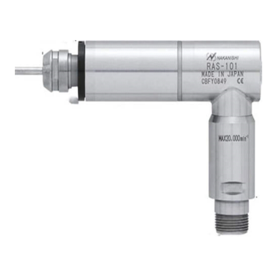
3 - 2 Outside view
(16.9)
75
Dust Proof Cover Area
Fig. 1 RAS-101
4 . CONNECTING THE SPINDLE TO THE MOTOR
CAUTION
・
Make sure your hands and all interlocking parts of the spindle and motor are clean before
connecting the motor to the spindle. This is critical to prevent contaminants from entering the
motor or spindle.
RAS-101 is drive (-) configuration clutch. The (-) drive spindles were designed to be used with (-)
・
drive motors and speed reducers.
Align the threads on the front end of the motor
and the rear end of the spindle, and turn the
spindle clockwise. If the drive shaft of the motor
does not engage the drive dog on the spindle,
the spindle could not be turned. DO NOT
FORCE. Turn the spindle back a few threads,
rotate the tool by hand to engage the drive
shaft and the drive dog, and make the final
turns with provided wrench .
5 . CHANGING THE TOOL
CAUTION
Do not tighten the collet chuck without inserting a tool or dummy bur, as this will damage the collet
chuck, spindle or chuck nut, causing difficulty removing the collet chuck.
① Set the provided 12mm wrench on the spindle.
② Place the provided 14mm wrench on the chuck nut and
turn it counterclockwise to loosen the collet chuck and
remove the tool. (The first turn will loosen the chuck nut,
but the tool will not release and turning will become stiff.
Keep turning through the stiffness and the collet chuck
will open.)
③ Clean the collet chuck and chuck nut, then insert the new
tool and tighten the collet chuck by turning clockwise. Do
not overtighten.
6 . REPLACING THE COLLET CHUCK
CAUTION
When installing the collet chuck in the chuck nut, make sure to fully engage the latch inside the
chuck nut to the groove on the collet chucks outer circumference area. In addition, remember that
if the collet chuck is attached without being engaged with the latch of the chuck nut, the collet
chuck cannot be removed and this may cause damage to the collet chuck or the spindle.
① Remove the tool according to the section
" 5. CHANGING THE TOOL " procedure
above and remove chuck nut assembly
(Fig. 5).
② The collet chuck and chuck nut are secured
by a groove in the collet chuck and a flange
in the chuck nut. To remove the collet chuck
hold the chuck nut in one hand and push
diagonally down on the collet chuck. The
collet chuck should be released (Fig. 6).
③ To install the collet chuck, hold the collet
chuck at a slight angle, and insert it into the
chuck nut (Fig. 7).
Press the collet chuck in the chuck nut by
positioning the collet chuck in the chuck nut
and pressing down on flat surface (Fig. 6).
Be sure to fully engage the latch inside
the chuck nut into the groove on the collet
chucks outer circumference area (Fig. 8).
Temperature
Humidity
MAX.75%
0 - 40°C
(No condensation)
-10 - + 50°C
10 - 85%
Standard Accessories
3.175mm (CHK-3.175)・・1pc.
・ Wrench
( 22 × 27 : RAS-151E ) or ( 20 × 24 : RAS-101 ) ・・1pc.
・ Operation Manual・・1set.
*The collet chuck and chuck nut are attached to the spindle.
-1.
-1
for the spindle.
0.5mm 〜 6.0mm in 0.1mm increments and
K-265
14
(16.9)
22.8
0
-0.01
Fig. 2 RAS-151E
RAS-101
Transmisson Cluch (-)
Chuck Nut
Chuck Nut
Fig. 5
Groove
Latch
Chuck Nut
Fig. 7
Atmospheric Pressure
700 - 1,060hPa
500 - 1,060hPa
2.35mm,
3.175mm,
6.35mm
75
14
Dust Proof Cover Area
30
0
-0.01
RAS-151E
Transmisson Cluch (
+
)
Turn
Tighten
Fig. 3
Tool
Loosen
Spindle Shaft
Tighten
Fig. 4
Tool
Wrench Seat
Loosen
Collet Chuck
Down
Spindle Shaft
Chuck Nut
Fig. 6
Latch
Collet Chuck
Fig. 8
Advertisement

Subscribe to Our Youtube Channel
Related Manuals for Nakanishi RAS-101


Summary of Contents for Nakanishi RAS-101
- Page 1 When installing a spindle to a fixed base, make sure the fixed base is grounded in order to motor or spindle. avoid the risk of an electric shock. RAS-101 is drive (-) configuration clutch. The (-) drive spindles were designed to be used with (-) ・ ⑦...
- Page 2 The final responsibility for ensuring holder's safety for use in a given application is left to the designer of the equipment in which NAKANISHI's spindle is installed. NAKANISHI offers spindles with a wide variety of capabilities and specifications. Please carefully check the spindle's specifications against the requirements of your equipment and verify suitability and safety of the Holder prior to initial use.
Need help?
Do you have a question about the RAS-101 and is the answer not in the manual?
Questions and answers