Advertisement
Quick Links
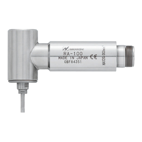
90
Angle Spindle
°
RA - 100
OPERATION MANUAL
Thank you for purchasing 90 ° Angle Spindle RA - 100 . This spindle is designed for use in corners, ID bores,
drilling and milling on the side of the workpiece and other areas that are difficult to work with a straight
type spindle. The E 2530 <Control Unit>, <Electric Motor> or <Air Motor> and <Air Line Kit with Lubricator
combination> are rquired to drive this spindle. Read this Operation Manual carefully before use. Also read
E 2530 <Control Unit>, <Electric Motor> or <Air Motor> and <Air Line Kit> Operation Manual.
1 . CAUTIONS FOR HANDLING AND OPERATION
■ Read these warnings and cautions carefully and only use in the manner intended.
■ These warnings and cautions are intended to avoid potential hazards that could result in personal injury or
damage to the device. These are classi¿ed as follows in accordance with the seriousness of the risk.
Class
A safety hazard could result in bodily injury or damage to the device if the
WARNING
safety instructions are not properly followed.
A hazard that could result in light or moderate bodily injury or damage
CAUTION
to the device if the safety instructions are not followed.
WARNING
①
This spindle is not a hand tool. It is designed to be used on CNC machines or special purpose
machines.
②
Do not touch the cutting tool while it is running. It is very dangerous.
③
Wear safety glasses, dust mask and use a protective cover around the spindle whenever the
spindle is rotating.
④
Never connect, disconnect or touch the Power Cord Plug and Motor Cord Connector with wet
hands. This may cause an electric shock.
⑤
Never operate or handle the spindle until you have thoroughly read the owner's manual and safe
operation has been con¿rmed.
1) To prevent injuries / damages, check the spindle and cutting tool for proper installation,
before operating the spindle.
2) Before disconnecting the spindle, always turn the control power off and turn the compressed
air supply to the control unit off. Then it is safe to remove the spindle.
⑥
When installing a tool, tighten the collet chuck correctly and check again the collet chuck
before use. Do not over - tighten the collet chuck. This may cause damage to the spindle.
⑦
Do not use bent, broken, chipped, out of round or sub-standard tools as they may cause
shatter or explode. Tool with fractures or a bent shank will cause injury to the operator. When
using a new tool, rotate it in a low speed and increase speed gradually for safety.
⑧
Do not exceed the maximum recommended allowable tool speed. For your safety, use speeds
below the maximum allowable speed.
⑨
Do not apply excessive force. This may cause tool slippage, tool damage, injury to the operator
or loss of concentricity and precision.
CAUTION
①
Do not exceed the maximum allowable motor speed 20,000min
②
The speed reducer is always used to connect between the air motor AM - 300 ‡ AM - 310 and
this spindle.
③
Do not drop or hit this spindle, as shock can damage to the internal components.
④
Be sure to clean the collet chuck, the inside of the spindle before replacing the tool. If ground
particles or metal chips stick to the inside of spindle or the collet chuck, damage to the collet
chuck or spindle can occur due to the loss of precision.
⑤
When cleaning a spindle, stop the motor and remove debris with a soft brush or a cloth. Do
not blow air into the spindle with compressed air as foreign particles or cutting debris may
get into the ball bearing.
⑥
Always clean the tool shank before installing the tool in the spindle.
⑦
When sizing the correct collet chuck size to the tool shank diameter, a tolerance of + 0 〜
- 0.01mm is strongly recommended. A tool shank within the + 0 〜 - 0.1mm range is mountable,
however, this may cause poor concentricity and or insuf¿cient tool shank gripping force.
⑧
Select suitable products or tools for all applications. Do not exceed the capabilities of the
spindle or tools.
⑨
Carefully direct coolant spray to the tool. Do not spray directly on the spindle body.
⑩
Stop working immediately when abnormal rotation or unusual vibration are observed.
Afterwards, please check the content of section " 10. TROUBLESHOOTING ".
⑪
Always check if the tool, collet chuck are damaged before and after operating.
⑫
If the collet chuck show signs of wear or damage, replace it before a malfunction or additional
damage occurs.
⑬
After installation, repair, initial operation, or long periods of non operation, please refer to
section " 8. BREAK-IN PROCEDURE " detailed in Table 1. When checking the spindle, no
vibration or unusual sound should be observed during rotation.
⑭
Do not disassemble, modify or attempt to repair this spindle. Additional damage will occur
to the internal components. Service must be performed by NSK NAKANISHI or an authorized
service center.
⑮
When using this spindle for mass production, please purchase the another spindle as a spare
in case of an emergency.
2 . FEATURES
① This spindle is ideal for use in applications that are not possible with straight type spindles.
② The spindle housing is made from precision ground, hardened, stainless steel (SUS) with outside mounting
diameters of
22.8mm.
③ Various sizes of collet chucks are available CH8 0.8mm - 3.0mm. Standard collet chuck is CH8 3.0mm or CH8
3.175mm. (For U.S. market CH8 3.175mm.)
OM-K0047E
Degree of Risk
-1
.
3 . SPECIFICATIONS AND DIMENSIONS
3 - 1 Speci¿cations
Model
For Air Motor
Maximum rotating
speed at the tool
For Electric Motor
For Air Motor
Maximun Motor
Rotation Speed
For Electric Motor
For Air Motor
Applicable Motor
For Electric Motor
001
Reduction Ratio
Standard Collet Chuck (CH8- 3.0)
Weight
CAUTION
Use less than the maximum allowable motor speed 20,000min
DO NOT exceed the maximun allowable motor speed 20,000min
Always use the reducer between the air motor (AM - 300 ‡ AM - 310) and RA - 100.
・ Collet Chuck
3.0mm ( CH8 - 3.0) or
(For U.S. market
3.175mm (CH8-3.175 ))
・ Wrench (7 × 5.5) ・・1 pcs.
・ Wrench (20 × 24) ・・1 pc.
< Option >
Collet Chuck ( CH8- □□ )
Metal Saw Axis (KCH-02)
For
3 - 2 Outside View
4 . CONNECTION TO THE MOTOR
CAUTION
Make sure your hands and all interlocking parts of the spindle and motor are clean before
connecting the motor to the spindle. This is critical to prevent contaminants from entering the
motor or spindle.
Align the threads on the front end of the reducer
and the rear end of the spindle, and turn the spindle
clockwise. If the drive shaft of the reducer does not
engage the drive dog on the spindle, the spindle could
not be turned. DO NOT FORCE. Turn the spindle
back a few threads, rotate the tool by hand to engage
the drive shaft and the drive dog, and make the ¿nal
turns with provided 20mm wrench. (Fig. 2)
5 . CHANGING THE TOOL
CAUTION
Do not tighten the collet chuck without inserting a tool or dummy bur as this will result in damage
to the collet chuck.
① Set the provided 8mm wrench on the spindle.
② Place the provided 5.5mm wrench on the collet
chuck and turn it counterclockwise to loosen the
collet chuck and remove the tool.
③ Clean the collet chuck, then insert the new tool
and tighten the collet chuck by turning clockwise.
Do not over-tighten. (Recommended tightening
torque : 3N・m)
6 . REPLACING THE COLLET CHUCK
① Remove the tool according to the section " 5.
CHANGING THE TOOL" procedure above. (Fig. 3)
② Place the provided 8mm wrench on the spindle
shaft, and turn the top of the collet chuck
counterclockwise to remove the collet chuck.
(Fig. 4)
③ Install the new collet chuck into the spindle by
turning it clockwise.
RA - 100
-1
2,870min
-1
7,490min
-1
7,650min
-1
20,000min
AM - 300R / L, AM - 300RA / LA, AM - 310R / Lm, AM - 310RA / LA
EM25 - 5000 - 4M / 5M / 8M, EM25 - 5000 - J4 / J5 / J8
1 / 2.67
3.0mm (For U.S. market
3.175mm (CH8 - 3.175 ))
271g
-1
.
-1
for the spindle.
Standard Accessories
3.175mm (CH8 - 3.175 )・・・1pc.
・ Wrench (8 × 5) ・・1 pcs.
・ Operation Manual・・1 set.
※ The collet chuck is attached to the spindle.
0.8mm 〜 3.0mm in 0.1mm increments and
2.35mm,
6 (I.D.) × 30mm (O.D.)
81.4
22.8
9
Fig. 1
Fig. 2
Tool
Wrench 8mm
Spindle Shaft
Fig. 3
Loosen
Spindle Shaft
Fig. 4
3.175mm
Transmission Clutch
Tighten
20
Turn
Collet Chuck
Wrench 5.5mm
Loosen
Tighten
Collet Chuck
Wrench 8mm
Advertisement

Related Manuals for Nakanishi RA-100


Summary of Contents for Nakanishi RA-100
- Page 1 ⑭ Do not disassemble, modify or attempt to repair this spindle. Additional damage will occur Fig. 3 to the internal components. Service must be performed by NSK NAKANISHI or an authorized service center. 6 . REPLACING THE COLLET CHUCK ⑮...
- Page 2 The ¿nal responsibility for ensuring holder's safety for use in a given application is left to the designer of the equipment in which NAKANISHI's spindle is installed. NAKANISHI offers spindles with a wide variety of capabilities and speci¿cations. Please carefully check the spindle's specifications against the requirements of your equipment and verify suitability and safety of the Holder prior to initial use.
Need help?
Do you have a question about the RA-100 and is the answer not in the manual?
Questions and answers