Table of Contents
Advertisement
Quick Links
Advertisement
Table of Contents

Related Manuals for SystemAir SYSHP MINI SPLIT HYDRO 06-16


Summary of Contents for SystemAir SYSHP MINI SPLIT HYDRO 06-16
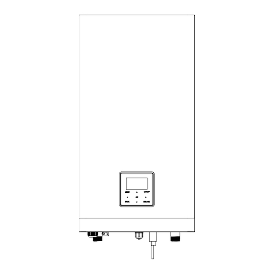
- Page 1 Installation and owner’s manual SYSHP MINI SPLIT HYDRO 06-16 R32 Split Heat Pump Indoor unit Original instructions Thank you very much for purchasing our product. Before use, please carefully read this manual and keep it for future reference.
-
Page 2: Table Of Contents
CONTENTS SAFETY PRECAUTIONS BEFORE INSTALLATION INSTALLATION SITE INSTALLATION PRECAUTIONS Dimensions Installation requirements Servicing space requirements Mounting the indoor unit Refrigerant pipe connection 5 GENERAL INTRODUCTION 6 ACCESSORIES TYPICAL APPLICATIONS Application 1 Application 2 OVERVIEW OF THE UNIT Disassembling the unit Main components Electronic control box Refrigerant pipework... - Page 3 MAINTENANCE AND SERVICE TROUBLE SHOOTING 12.1 General guidelines 12.2 General symptoms Operation parameter 12.3 Error codes 12.4 TECHNICAL SPECIFICATIONS INFORMATION SERVICING...
- Page 4 Basic Customized CN24 CN28 CN16 CN21 CN13 Electric Control Box CN15 CN29 CN18 CN25 CN42 CN40 DIS1 CN31 CN41 CN22 CN35 CN36 CN17 Electric Control Box CN24 CN28 CN16 CN11 CN30 CN21 CN13 CN15 CN29 CN18 CN42 CN25 CN40 DIS1 CN31 Terminal Block CN41...
-
Page 5: Safety Precautions
1 SAFETY PRECAUTIONS The precautions listed here are divided into the following types.They are quite important, so be sure to follow them carefully.Read these instructions carefully before installation. Keep this manual in a handy for future preference. Meanings of DANGER, WARNING, CAUTION and NOTE symbols. DANGER Indicates an imminently hazardous situation which if not avoided, will result in death or serious injury. - Page 6 Special requirements for R32 WARNING Do NOT have refrigerant leakage and open flame. Be aware that the R32 refrigerant does NOT contain an odour. WARNING The appliance shall be stored so as to prevent mechanical damage and in a well-ventilated room without continuously operating ignition sources (example:open flames,an operating gas appliance) and have a room size as specified below.
- Page 7 Input from installer: start ▪ Area of adjacent room B (A ) (m roomB Use table 2 in page5 to calculate the Input from installer: total minimum floor area ▪ Total refrigerant charge (m )(kg) )required total mintotal ▪ Area of room A (A roomA refrigerant charge (m ≥...
- Page 8 Table 1-Maximum refrigerant charge allowed in a room:indoor unit Maximum refrigerant charge in a room(m )(kg) Maximum refrigerant charge in a room(m )(kg) room room H=1800mm H=1800mm 1.02 2.05 2.29 1.45 1.77 2.51 NOTE For wall mounted models, the value of “Installation height (H)” is considered 1800 mm to comply to IEC 60335-2-40:2013 A1 2016 Clause GG2.
- Page 9 DANGER Before touching electric terminal parts, turn off power switch. When service panels are removed, live parts can be easily touched by accident. Never leave the unit unattended during installation or servicing when the service panel is removed. Do not touch water pipes during and immediately after operation as the pipes may be hot and could burn your hands.
- Page 10 CAUTION Install the power wire at least 3 feet (1 meter) away from televisions or radios to prevent interference or noise. (Depending on the radio waves, a distance of 3 feet (1 meter) may not be sufficient to eliminate the noise.) Do not wash the unit.
-
Page 11: Before Installation
2 BEFORE INSTALLATION Before installation Be sure to confirm the model name and the serial number of the unit. CAUTION Frequency of Refrigerant Leakage Checks - For unit that contains fluorinated greenhouse gases in quantities of 5 tonnes of CO equivalent or more,but of less than 50 tonnes of CO equivalent,at least every 12 months, or where a leakage detection system is installed, at least every 24... - Page 12 CAUTION The indoor unit should be installed in an indoor water proof place, or the safety of the unit and the operator cannot be ensured. The indoor unit is to be wall mounted in an indoor location that meets the following requirements: The installation location is frost-free.
-
Page 13: Installation Precautions
4 INSTALLATION PRECAUTIONS 4.1 Dimensions Dimensions of the wall bracket: 3× 12 unit:mm Fig.4-1 Dimensions of the unit: Fig.4-2 unit:mm NAME Refrigerant gas connection5/8"-14UNF Refrigerant gas connection 5/8"-14UNF Refrigerant liquid connection 1/4"(60) or 3/8"(100/160) -14UNF Drainage Water Inlet R1” Water Outlet R1” 4.2 Installation requirements The indoor unit is packed in a box. -
Page 14: Servicing Space Requirements
WARNING Do not grasp the control box or pipe to lift the unit! CN24 CN28 CN16 CN21 CN13 CN15 CN29 CN18 CN25 CN42 CN40 DIS1 CN31 CN41 CN22 CN35 CN36 CN17 CN11 CN30 Fig.4-3 4.3 Servicing space requirements ≥300 ≥350 ≥500 Fig.4-4 unit:mm... -
Page 15: Mounting The Indoor Unit
Mounting the indoor unit Fix the wall mounting bracket to the wall using appropriate plugs and screws. Make sure the wall mounting bracket is horizontal level. Pay special attention to prevent overflow of the drain pan. Hang the indoor unit on the wall mounting bracket. two persons two persons two persons... -
Page 16: General Introduction
5 GENERAL INTRODUCTION These units are used for both heating and cooling applications and domestic hot water tanks.They can be combined with fan coil units, floor heating applications, low temperature high efficiency radiators, domestic hot water tanks (field supply) and solar kits (field supply). -
Page 17: Accessories
In cooling mode, the water flowing temperature 6 ACCESSORIES (TW_out) range in different outdoor temperature (T4) is list below: Installation Fittings Quantity Shape Name Installation and owner’s manual(this book) Operation manual M16 Copper Nut Tamper M9 Copper Nut Tamper Operation range by heat pump with possible limitation and protection. M6 Copper Nut Tamper In heating mode, the water flowing temperature (TW_out) range in different outdoor temperature (T4) is... -
Page 18: Typical Applications
7 TYPICAL APPLICATIONS The application examples given below are for illustration only. 7.1 Application 1 Indoor Outdoor 2.11 FHL1 FHL2 FHLn 2.10 14.2 14.1 Modbus 14.3 Code Assembly unit Code Assembly unit Outdoor unit Expansion vessel (Field supply) Hydraulic module Domestic hot water tank (Field supply) TBH: Domestic hot water tank booster 14.1... -
Page 19: Domestic Water Heating
Space heating The ON/OFF signal and operation mode and temperature setting are set on the user interface. P_o(6) keeps running as long as the unit is ON for space heating, SV1(4) keeps OFF. Domestic water heating The ON/OFF signal and target tank water temperature (T5S) are set on the user interface. P_o(6) stops running as long as the unit is ON for domestic water heating, SV1(4) keeps ON. -
Page 20: Application
7.2 Application 2 ROOM THERMOSTAT Control for Space heating or cooling need to be set on the user interface. It can be set in three ways: MODE SET/ONE ZONE/DOUBLE ZONE. The indoor unit can be connected to a high voltage room thermostat and a low voltage room thermostat. - Page 21 7.2.2 Mode set control Indoor Outdoor FCU1 FCU2 FCUn 2.11 2.10 FHL1 FHL2 FHLn Modbus Code Assembly unit Code Assembly unit Outdoor unit Shut-off valve (Field supply) Indoor unit Filling valve (Field supply) User interface Drainage valve (Field supply) Balance tank (Field supply) Collector/distributor (Field supply) Automatic air purge valve Bypass valve (Field supply)
- Page 22 7.2.3 Double zone control Indoor Outdoor RAD.1 ZONE1 2.11 RAD.2 2.10 RAD.n ZONE2 8.1 8.2 FHL1 FHL2 FHLn Modbus Code Assembly unit Code Assembly unit Outdoor unit Filter (Accessory) Indoor unit Shut-off valve (Field supply) User interface Filling valve (Field supply) Balance tank (Field supply) Drainage valve (Field supply) Automatic air purge valve...
- Page 23 The floor heating loops require a lower water temperature in heating mode compared to radiators or fan coil units. To achieve these two set points, a mixing station is used to adapt the water temperature according to requirements of the floor heating loops. The radiators are directly connected to the unit water circuit and the floor heating loops are after the mixing station.
-
Page 24: Overview Of The Unit
8 OVERVIEW OF THE UNIT 8.1 Disassembling the unit The indoor unit cover can be removed by removing the 2 screws and unhitching the cover. CAUTION Make sure to fix the cover with the screws and nylon washers when installing the cover (screws are delivered as accessory) .Parts inside the unit can be hot. - Page 25 14.2 14.2 14.1 14.1 Basic Customized Code Assembly unit Explaination Remaining air in the water circuit will be automatically removed Automatic air purge valve via the automatic air purge valve. Expansion vessel (8 L) Refrigerant gas pipe Refrigerant liquid pipe Four temperature sensors determine the water and refrigerant Temperature sensors temperature at various points.
-
Page 26: Electronic Control Box
8.3 Electronic control box PCB of indoor unit CN24 CN21 CN28 CN16 CN32 CN13 CN15 CN29 CN18 CN25 CN42 CN24 CN21 CN28 CN16 CN40 CN32 DIS1 CN13 CN31 CN41 CN15 CN29 CN18 CN25 CN22 CN42 CN35 CN40 DIS1 CN36 CN31 CN41 CN17 CN22... - Page 27 8.3.1 Main control board of indoor unit CN24 CN21 CN28 CN16 CN32 CN13 CN15 CN29 CN18 CN25 CN42 CN40 DIS1 CN31 CN41 CN22 CN35 CN36 CN17 CN11 CN30 Order Port Code Assembly unit Order Port Code Assembly unit POWER M1 M2 Port for remote switch CN21 Port for power supply...
-
Page 28: Refrigerant Pipework
8.4 Refrigerant pipework For all guidelines, instructions and specifications regarding refrigerant pipework between the indoor unit and outdoor unit, please refer to "Installation and owner’s manual (M-thermal split outdoor unit)". CAUTION When connecting the refrigerant pipes, always use two wrenches/spanners for tightening or loosening nuts! Failure to do so can result in damaged piping connections and leaks. - Page 29 8.5.1 Check the water circuit The unit is equipped with a water inlet and water outlet for connection to a water circuit. This circuit must be provided by a licensed technician and must comply with local laws and regulations. The unit is only to be used in a closed water system. Application in an open water circuit can lead to excessive corrosion of the water piping.
- Page 30 Before continuing installation of the unit, check the following: The maximum water pressure ≤ 3 bar. The maximum water temperature ≤ 70°C according to safety device setting. Always use materials that are compatible with the water used in the system and with the materials used in the unit. Ensure that components installed in the field piping can withstand the water pressure and temperature.
- Page 31 8.5.3 Water circuit connection Water connections must be made correctly in accordance with labels on the indoor unit, with respect to the water inlet and water outlet. CAUTION Be careful not to deform the unit’s piping by using excessive force when connecting the piping. Deforming the piping can cause the unit to malfunction.
-
Page 32: Filling Water
Water may enter into the flow switch and cannot be drained out and may freeze when the temperature is low enough. The flow switch should be removed and dried, then can be reinstalled in the unit. There need drying NOTE 1.Counterclockwise rotation, remove the flow switch. -
Page 33: Water Piping Insulation
8.7 Water piping insulation The complete water circuit including all piping, water piping must be insulated to prevent condensation during cooling operation and reduction of the heating and cooling capacity as well as prevention of freezing of the outside water piping during winter. The insulation material should at least of B1 fire resistance rating and complies with all applicable legislation. - Page 34 AHS1 AHS2 1OFF 2OFF DFT2 DFT1 IBH1 3OFF CN11 CN30 25 T Outdoor Indoor Modbus Code Assembly unit Code Assembly unit Outdoor unit SV2: 3-way valve (field supply) SV1: 3-way valve for domestic hot Solar energy kit (field supply) water tank (field supply) User interface Booster heater High voltage room thermostat (field supply)
- Page 35 Description AC/DC Required number of conductors Maximum running current Item Solar energy kit signal cable 200mA 200mA User interface cable Room thermostat cable 200mA(a) Solar pump control cable 200mA(a) Outside circulation pump control cable 200mA(a) 200mA(a) DHW pump control cable 200mA(a) SV2: 3-way valve control cable SV1: 3-way valve control cable...
-
Page 36: Safety Device Requirements
Use the correct screwdriver to tighten the terminal screws. Small screwdrivers can damage the screw head and prevent appropriate tightening. Over-tightening the terminal screws can damage the screws. Attach a ground fault circuit interrupter and fuse to the power supply line. In wiring, make certain that prescribed wires are used, carry out complete connections, and fix the wires so that outside force cannot affect the terminals. - Page 37 L2 L3 INDOOR UNIT INDOOR UNIT INDOOR UNIT POWER SUPPLY POWER SUPPLY POWER SUPPLY (Basic) 1-phase 3KW backup heater 3-phase 3/6/9KW backup heater Basic Unit 3KW-1PH 3KW-3PH 6KW-3PH 9KW-3PH Wiring size(mm Stated values are maximum values (see electrical data for exact values). CAUTION When connecting to the power supply terminal, use the circular wiring terminal with the insulation casing (see Figure 8.1).
- Page 38 8.8.6 Connection for other components Unit 4-16kw P_c P_o P_s P_d AHS1 AHS2 1OFF 2OFF IBH1 N 3ON DFT2 3OFF DFT1 CN11 CN30 Code Code Print Print Connect to Connect to Solar energy input ① signal Wired controller ① Room thermostat input ②...
- Page 39 1) For solar energy input signal 25 26 27 28 1 2 3 4 5 1 2 3 4 5 6 7 8 9 10 11 12 29 30 31 32 1 2 3 4 5 6 7 8 9 10 13 14 15 16 17 6 7 8 9 10 CN30...
- Page 40 4) For remote shut down: CN24 CN21 CN28 CN16 CN32 CN13 CN15 CN29 CN18 CN25 CN42 CN40 DIS1 25 26 27 28 CN31 1 2 3 4 5 CN41 29 30 31 32 6 7 8 9 10 CN11 CN30 CN22 CN35 CN36...
- Page 41 Voltage 220-240VAC Maximum running current(A) Wiring size(mm 0.75 25 26 27 28 1 2 3 4 5 29 30 31 32 6 7 8 9 10 Control port signal type Type 2 CN11 CN30 a) Procedure Connect the cable to the appropriate terminals as shown in the picture.
- Page 42 Room thermostat type2 (Low voltage): CN24 CN24 CN21 CN21 CN28 CN28 CN16 CN16 CN32 CN32 CN13 CN13 CN15 CN15 CN29 CN29 CN18 CN18 CN25 CN25 CN42 CN42 CN40 CN40 DIS1 DIS1 CN31 CN31 CN41 CN41 CN22 CN22 CN35 CN35 CN36 CN36 CN17 CN17...
- Page 43 C.2 When unit detect voltage is 12VDC between CL and COM, 8) For additional heat source control: zone2 turn on according to climate temp curve. When unit detect voltage is 0V between CL and COM, zone2 turn off. C.3 When HT-COM and CL-COM are detected as 0VDC, unit turn off.
- Page 44 Voltage 220-240VAC Maximum running current(A) Wiring size(mm 0.75 Control port signal type 25 26 27 28 Type 1 1 2 3 4 5 29 30 31 32 6 7 8 9 10 CN11 CN30 10) For outside circulation pump P_o: 25 26 27 28 1 2 3 4 5...
-
Page 45: Start-Up And Configuration
1. when EVU signal is on, the unit operate as below: 2. When EVU signal is off, and SG signal is on, the unit operate normally. DHW mode turn on, the setting temperature will be changed to 70℃ 3. When EVU signal is off, SG signal is off, the DHW mode is off, and automatically, and the TBH operate as below:T5<69. -
Page 46: Initial Start-Up At Low Outdoor Ambient Temperature
9.2 Initial start-up at low outdoor ambient temperature During initial start-up and when water temperature is low, it is important that the water is heated gradually. Failure to do so may result in concrete floors cracking due to rapid temperature change. Please contact the responsible cast concrete building contractor for further details. -
Page 47: Setting The Pump
9.4 Setting the pump The pump is contolled via a digital low-voltage pulse-width modulation signal which means that the speed of rotation depends on the input signal.The speed changes as a function of the input profile. The relationships between the head and the water flow rated,the PMW Return and the water flow rated are shown in the graph below. -
Page 48: Field Settings
Failure diagnosis at first installation If nothing is displayed on the user interface, it is necessary to check for any of the following abnormalities before diagnosing possible error codes. -Disconnection or wiring error (between power supply and unit and between unit and user interface). -The fuse on the PCB may be broken. -
Page 49: Dhw Mode Setting
About FOR SERVICEMAN FOR SERVICEMAN 13. AUTO RESTART "FOR SERVICEMAN" is designed for the installer to set 14. POWER INPUT LIMITATION the parameters. 15. INPUT DEFINE 16. CASCADE SET 17. HMI ADDRESS SET Setting the composition of equipment. Setting the parameters. ENTER How to go to FOR SERVICEMAN Go to MENU>... -
Page 50: Cool Mode Setting
9.5.3 HEAT MODE SETTING 1 DHW MODE SETTING Go to MENU>FOR SERVICEMAN> 3.HEAT MODE 1.16 t_DI_MAX SETTING. Press OK. The following pages will be 1.17 t_DHWHP_RESTRICT 30 MIN displayed: 1.18 t_DHWHP_MAX 120 MIN 1.19 DHWPUMP TIME RUN 3 HEAT MODE SETTING 1.20 PUMP RUNNING TIME 5 MIN 3.1 HEAT MODE... - Page 51 9.5.5 TEMP. TYPE SETTING About TEMP. TYPE SETTING ◄ The TEMP. TYPE SETTING is used for selecting whether the water flow temperature or room temperature is used to control the ON/OFF of the heat pump. When ROOM TEMP. is enabled, the target water flow temperature will be calculated from climate-related curves .
-
Page 52: Holiday Away Setting
9.5.7 Other HEATING SOURCE In this case, the setting value of zone 1 is T1S,the setting value of zone 2 is T1S2. The OTHER HEATING SOURCE is used to set the parameters of the backup heater, additional heating If you set DOUBLE ZONE and ROOM TEMP. to YES, sources and solar energy kit. -
Page 53: Restore Factory Settings
9 SERVICE CALL If YES is selected, the following pages will be displayed: PHONE NO. *************** MOBILE NO. ****************** 11 TEST RUN 11.1 POINT CHECK 11.2 AIR PURGE 11.3 CIRCULATED PUMP RUNNING CONFIRM ADJUST 11.4 COOL MODE RUNNING 11.5 HEAT MODE RUNNING The number displayed on the user interface is the phone ENTER number of your local dealer. -
Page 54: Special Function
When in air purge mode, SV1 will open, SV2 will close. During HEAT MODE test running, the default target outlet 60s later the pump in the unit (PUMPI) will operate for water temperature is 35°C. The IBH (internal backup 10min during which the flow switch will not work. After the heater) will turn on after the compressor runs for 10 min. - Page 55 Go to MENU> FOR SERVICEMAN> 12.SPECIAL During preheating for floor, all the buttons except OK are FUNCTION. invalid. If you want to turn off the preheating for floor, please press OK. Before floor heating, if a large amount of water remains on the floor, the floor may be warped or even rupture during The following page will be displayed: floor heating operation, in order to protect the floor, floor...
-
Page 56: Auto Restart
During floor drying, all the buttons except OK are invalid. The AUTO RESTART function reapplies the user When the heat pump malfunctions, the floor drying mode interface settings at the time of the power supply failure. If will turn off when the backup heater and additional this function is disabled, when power returns after a heating source is unavailable. - Page 57 9.5.16 Setting parameters The parameters related to this chapter are shown in the table below. Setting Order number Code State Default Minumum Maximum Unit interval DHW MODE Enable or disable the DHW mode:0=NON,1=YES DISINFECT Enable or disable the disinfect mode:0=NON,1=YES DHW PRIORITY Enable or disable the DHW priority mode:0=NON,1=YES DHW PUMP...
- Page 58 HEAT MODE Enable or disable the heating mode The refresh time of climate related curves for heating t_T4_FRESH_H hours mode The maximum ambient operating temperature for heating T4HMAX ℃ mode The minimum ambient operating temperature for heating T4HMIN ℃ mode dT1SH The temperature difference for starting the unit (T1) ℃...
- Page 59 12.4 t_DRYUP The day for w arming up during floor drying up The continue days in high temperature during floor 12.5 t_HIGHPEAK drying up The day of dropping temperature during floor drying 12.6 t_DRYD The target peak temperature of w ater flow during 12.7 T_DRYPEAK °C...
-
Page 60: Test Run And Final Checks
10 TEST RUN AND FINAL The following checks must be performed at least once a year by qualified person. CHECKS Water pressure Check the water pressure, if it is below 1 bar,fill water The installer is obliged to verify correct operation of unit to the system. -
Page 61: Trouble Shooting
12 TROUBLE SHOOTING This section provides useful information for diagnosing and correcting certain troubles which may occur in the unit. This troubleshooting and related corrective actions may only be carried out by your local technician. 12.1 General guidelines Before starting the troubleshooting procedure, carry out a thorough visual inspection of the unit and look for obvious defects such as loose connections or defective wiring. - Page 62 Symptom 3: Pump is making noise (cavitation) POSSIBLE CAUSES CORRECTIVE ACTION There is air in the system. Purge air. • Check on the manometer that there is sufficient water pressure. The water pressure must be > 1 bar (water is cold). •...
-
Page 63: Corrective Action
Symptom 8: DHW mode can’t change to Heat mode immediately POSSIBLE CAUSES CORRECTIVE ACTION • Set "t_DHWHP_MAX" to minimum value, the suggested value is 60min. • If circulating pump out of unit is not controlled by unit, try to Heat exchanger for space connect it to the unit. - Page 64 OPERATION PARAMETER OPERATION PARAMETER OPERATION PARAMETER FAN SPEED 600R/MIN TW_O PLATE W-OUTLET TEMP. 35°C T3 OUTDOOR EXCHARGE TEMP. 5°C IDU TARGET FREQUENCY 46Hz TW_I PLATE W-INLET TEMP. 30°C T4 OUTDOOR AIR TEMP. 5°C FREQUENCY LIMITED TYPE T2 PLATE F-OUT TEMP. 35°C TF MODULE TEMP.
-
Page 65: Error Codes
12.4 Error codes When a safety device is activated, an error code will be displayed on the user interface. A list of all errors and corrective actions can be found in the table below. Reset the safety by turning the unit OFF and back ON. In case this procedure for resetting the safety is not successful, contact your local dealer. - Page 66 ERROR MALFUNCTION FAILURE CAUSE CODE OR PROTECTION AND CORRECTIVE ACTION 1. The EEprom parameter is error, rewrite the EEprom data. 2. EEprom chip part is broken, change a new EEprom chip Indoor unit EEprom failure part. 3. main control board of indoor unit is broken, change a new PCB.
- Page 67 ERROR MALFUNCTION FAILURE CAUSE CODE OR PROTECTION AND CORRECTIVE ACTION Three times “PP” The same to "PP". protection and Tw_out< 7℃ 1.Check the resistance of the sensor. 2.The Tbt1 sensor connector is loosen,reconnect it. Buffer tank up 3.The Tbt1 sensor connector is wet or there is water in,remove temp.sensor(Tbt1) fault the water ,make the connector dry.Add waterproof adhesive.
-
Page 68: Technical Specifications
13 TECHNICAL SPECIFICATIONS Indoor unit model 220-240V~ 50Hz Power supply Rated input 0.4A 0.4A 0.4A Rated Current Refer to the technical data Norminal capacity 420x790x270 Dimensions (W×H×D)[mm] 525x1050x360 Packing (W×H×D)[mm] Plate heat exchanger Heat exchanger Electric heater 5.0L Internal water volume 0.3MPa Rated water pressure Filter mesh... - Page 69 Indoor unit model 60 (3kW Heater) 100 (3kW Heater) 160 (3kW Heater) 60 (9kW Heater) 100 (9kW Heater) 160 (9kW Heater) 220-240V~ 50Hz 380~415V 3N~ 50Hz Power supply 3095W 3095W 3095W 9095W 9095W 9095W Rated input 13.5A 13.5A 13.5A 13.3A 13.3A 13.3A Rated Current...
-
Page 70: Information Servicing
14 INFORMATION SERVICING 1) Checks to the area Prior to beginning work on systems containing flammable refrigerants, safety checks are necessary to ensure that the risk of ignition is minmised. For repair to the refrigerating system, the following precautions shall be complied with prior to conducting work on the system. - Page 71 10) Repairs to sealed components a) During repairs to sealed components, all electrical supplies shall be disconnected from the equipment being worked upon prior to any removal of sealed covers, etc. If it is absolutely necessary to have an electrical supply to equipment during servicing, then a permanently operating form of leak detection shall be located at the most critical point to warn of a potentially hazardous situation.
- Page 72 Ensure that contamination of different refrigerants does not occur when using charging equipment. Hoses or lines shall be as short as possible to minimize the amount of refrigerant contained in them. Cylinders shall be kept upright. Ensure that the refrigeration system is earthed prior to charging the system with refrigerant. Label the system when charging is complete(if not already).
- Page 73 ANNEX A: Refrigerant cycle Basic Customized Description Description Item Item Water Side Heat Exchanger Expansion vessel (Plate Heat Exchange) Circulating pump Flow switch Manometer Refrigerant liquid line temperature sensor Pressure relief valve Refrigerant gas line temperature sensor Internal backup heater Water outlet temperature sensor Total outlet temperature sensor Water inlet temperature sensor...
- Page 74 NOTE...
- Page 75 NOTE...
- Page 76 Systemair srl Via XXV Aprile, 29 20825 Barlassina (MB) Italy Tel. +39 0362 680 1 Fax +39 0362 680 693 www.systemair.com As part of our ongoing product improvement programme, our products are subject to change without prior notice. Non contractual photos.
Need help?
Do you have a question about the SYSHP MINI SPLIT HYDRO 06-16 and is the answer not in the manual?
Questions and answers