Table of Contents
Advertisement
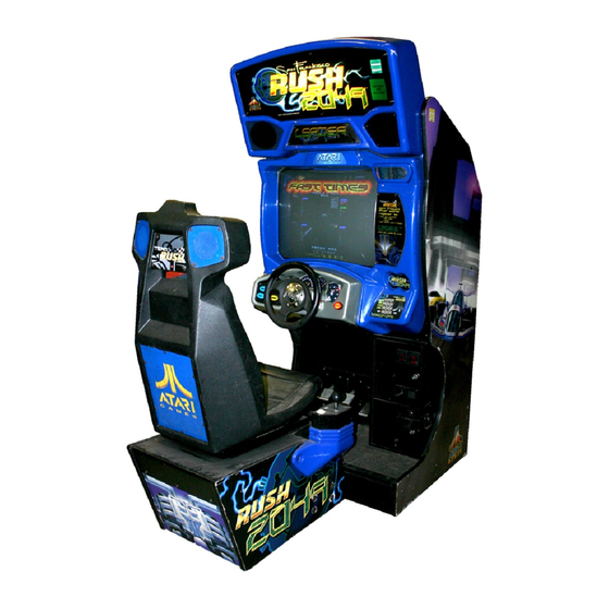
SAN FRANCISCO
RUSH 2049'"
SAFETY, SPECIFICATIONS,
INSPECTION & INSTALLATION
NOTICE:
This manual is subject to change without notice. Atari reserves the right to make
improvements in equipment function, design, or components as progress in engineering or
manufacturing methods may warrant.
Fill out and mail in the Game Information Card. Include the game serial number from the label
o n the rear of the cabinet. For your records, write the game serial number in the manual.
Advertisement
Table of Contents

Related Manuals for Atari San Francisco Rush 2049


Summary of Contents for Atari San Francisco Rush 2049
- Page 1 SAFETY, SPECIFICATIONS, INSPECTION & INSTALLATION NOTICE: This manual is subject to change without notice. Atari reserves the right to make improvements in equipment function, design, or components as progress in engineering or manufacturing methods may warrant. Fill out and mail in the Game Information Card. Include the game serial number from the label...
-
Page 2: Safety Instructions
SAFETY INSTRUCTIONS The following safety instructions apply to operators and service personnel. Read these instructions before preparing your game for play. Other safety instructions appear throughout this manual. DEFINITIONS OF SAFETY TERMS DANGER indicates imminent hazard. If you fail to avoid this hazard, it WILL cause death or serious injury. WARNING indicates a potential hazard. -
Page 3: Product Specifications
drop a WARNING: HANDLE FLUORESCENT TUBE AND CRT WITH CARE. FRAGILE fluorescent tube or CRT and it breaks, it will implode! Shattered glass can fly eight feet or more from the implosion. Set the 110/220VAC selector on the CAUTION: CHECK POWER SELECTOR, LAMP. power supply for the correct line voltage. -
Page 4: Product Configuration
PRODUCT CONFIGURATION Stand-Alone Units Each game is ready to play right out of the shipping carton. Use the game menu system to set player variables in advance, or you can accept the factory settings and leave the choices to the players. Tandem Units Linking allows players to compete against each other (on one course). - Page 5 Remove and set aside items from the shipping containers. Remove all packing material. Inspect for damage. Check the main cabinet exterior, pedestal, shifter, and all of the seat surfaces. Remove the keys from the steering wheel. Unlock and open the coin and cash doors. Electrical cords, mechanical components, and game spare parts are packed inside the cash box.
- Page 6 The hasp bracket is in the spare parts bag. Remove four screws from the sides of the cabinet rear door. Unlock and remove the rear door. Remove the two lock bracket nuts from inside the cabinet, above the rear door opening. Slide the hasp onto the bolts so that it protrudes from the hole in the back of the cabinet.
- Page 7 C A B I N E T B A S E C A B I N E T B A S E M O U N T I N G R A I L M O U N T I N G R A I L P E D E S T A L M O U N T I N G H O L E S P E D E S T A L M O U N T I N G H O L E S ( N U T S ) ( N U T S )
-
Page 8: Seat Position
SEAT POSITION A D J U S T L E V E R SEAT TRAVEL AND DETENT POSITIONS [ ] 15. Lower each seat pedestal leg leveler until the cabinet is stable and level. Adjust the levelers raise the wheels up off the floor. Distribute the pedestal’s weight equally on each leg leveler. Sit in the driver’s seat. - Page 9 POWER SUPPLY XHAU CHECK CABINET AIR FLOW [ ] 20. Check the cabinet to be certain that the cooling fan air paths are not blocked. The power supply has rear vents. The game electronics fan is mounted at the lower left corner of the enclosure directly behind the rear door air inlet.
- Page 10 F L A N G E G R I P N U T SECURITY BRACKET RIGHT C O I N V A U L T S E C U R I T Y B R A C K E T . L E F T SECURITY BRACKET INSTALLATION To install the optional coin security brackets, open the doors.
- Page 11 CABINET ARRA’? Multiple cabinets should be attached together to form a game array. Each cabinet comes with its own mounting hardware to mechanically connect the cabinets. See the following pages for linking instructions. Install the cabinet casters, leg levelers, seat pedestal, etc., as described on previous pages. Place the completed cabinets next to each other, leaving sufficient space to remove and install bolts.
- Page 12 LINKING Connect games together electronically to permit simultaneous competition between players. The linking cables are factory installed in each cabinet. Crossover couplers are supplied in the spare parts. Once connected, games can operate individually (as before) or in linked mode as players desire. Players quickly learn to associate joined cabinets with linked operation.
-
Page 13: Features And Operation
FEATURES & OPERATION NOTICE Information in this manual is subject to change without notice. ATARI reserves the right to make improvements in equipment function, design, or components as progress in engineering or manufacturing methods may warrant. Fill out and mail in the Game Registration card. Include the game serial number from the label on the rear of the... - Page 14 FEATURES PREVIEW are presented with laps from several different camera angles and spectator viewpoints. Use the Preview feature to see some of the fast grooves for curves and tunnels. Tap the MUSIC button during any of these scenes to skip ahead to the next scene. Press and hold MUSIC for five seconds to continue a particular scene, best lines through curves, or to see copyright and team credits.
- Page 15 SHIFTER Players may choose between manual and automatic transmissions. Manual shifting usually produces better speed control, resulting in faster lap times. The operator may set all games to shift as automatic transmission type if players agreed or a particular style of competition requires this feature. The previous button options from car selection (see CARS) remain in effect during shifter selection.
- Page 16 OPERATOR ALERT SIGNAL When the computer analyzes the error log and determines an on-going condition exists for more than three consecutive games, it activates a visual signal. The signal appears as a red dot in the lower left corner of the Attract screens (refer to Alert Mode under Game Operation on the following page). This alerts the operator or attendant that the game performance is compromised.
-
Page 17: Game Operation
GAME OPERATION INITIAL START UP Switch ON power to the game. Automatic self-diagnostic tests verify and report the condition of the hard disk drive, memory, controls, etc. Messages display while the software is loading. Error messages remain until the ABORT button is pressed. If there are no errors, the game enters Attract Mode automatically. NOTE: When faults are detected, the game halts and an error message may appear on the screen. -
Page 18: Player Controls
PLAYER CONTROLS Player controls allow a driver to pilot the cars around the track. These controls mimic those found in a real car. Many of these controls are also used when setting up a custom car or entering player information. VIEW 1 button permits players to see the course from the front of the car during the race. -
Page 19: Operator Controls
OPERATOR CONTROLS Operators have lock-and-key access to the menu system for statistics, adjustments, and testing to prevent tampering. On-screen messages guide the operator through menu options. The ON/OFF SWITCH is located next to line cord on the power supply. The switch is on the cabinet rear. The MONITOR REMOTE ADJUSTMENTS are located inside the coin vault. -
Page 20: Power-On Self-Tests
POWER-ON SELF-TESTS The Power-On Self-Tests let the game calibrate the player controls. Don’t touch the wheel during the test. These basic tests run automatically. They detect faults that would prevent proper game operation. POWER-ON SELF-TESTS SCREEN The Power-On Self-Test (POST) runs whenever you switch power off and on. The POST also runs whenever the processor resets. -
Page 21: Switches And Jumpers
SERVICE REQUIRED TESTS Each time the game returns to its Attract Mode the program checks the error log. If errors are found, the Operator Alert Signal will appear at the lower left corner of the Attract screens if the computer verifies a fault. - Page 22 NOTES 2-10...
- Page 23 C H A P T E R PARTS Warning USE OF NON-ATARI PARTS OR CIRCUIT MODIFICATIONS MAY CAUSE SERIOUS INJURY OR EQUIPMENT DAMAGE! USE ONLY ATARI AUTHORIZED PARTS. . For safety and reliability, substitute parts and modifications are not recommended.
- Page 24 A-23188 MAIN CABINET ASSEMBLY FRONT VIEW MARQUEE A S S E M B L Y (SEE DETAIL DRAWING) I N S T R U C T I O N L I G H T A S S E A I L A W I N P A N E L B R A C K E T...
- Page 25 A-23188 MAIN CABINET ASSEMBLY REAR VIEW 01-15079 MAROUEE SUPPORT BRACKET 4020-01100-20 HEADER S C R E W 1/4-20x1 ( F O R U . S . M O D E L S O N L Y ) TAMPER RESISTANT MAROUEE S C R E W #8x5/8 T R X ASSEM...
- Page 26 CABINET AND PEDESTAL ASSEMBLY FRONT VIEW 4020-01070-20 SCREW 1,/4-20x 1 - l/4 HH 470 1-00005-006 LOCKWASHER l/4 S P L I T FLAT WASHER PPORT F L A T W A S H E R - - - - - .
- Page 27 CASTER AND LEVELER ASSEMBLIES BOTTOM VIEW 4008-01113-16 04-10633 SWIVEL MOUNTING BRACKET 4608-01219-11 20-10360 SCREW #8x1 l/16 PINHEAD SWIVEL CASTER CASTER SHAFT WOOD SCREW B O T T O M V I E W O F C A B I N E T A S S E M B L Y 4008-01113-16 - S C R E W P L - H W H...
- Page 28 A-23191 MONITOR COVER ASSEMBLY FRONT VIEW 315399-z ATARI GAMES DECAL MIRROR DECAL 315397.1 . BEZEL PANEL INSTRUC SCREW 4-40x5/16 P-PH-S TAMPER RESISTANT DECAL...
- Page 29 A-231 89 MARQUEE LIGHTBOX ASSEMBLY FRONT VIEW FLUORESCENT LAMP ASSEMBLY 4020-01070-20 SCREW 1/4-20x1 20-10560 H I N G E FLAT WASHER 265x.875x 4701-00005-00 4008-01113-06 --- .._____ LOCKWASHER l/4 SPLIT S C R E W 8 - 3 2 x 3 / 8 PL-HWH LEADER LIGHT ASSEMBLY (SEE DETAIL DRAWING)
-
Page 30: Front View
ASSEMBLY A-23199 SEAT PEDESTAL FRONT VIEW SEAT ASSEMBLY ( S E E DETAIL DRAWIN SEAT SLIDE ASSEMBLY S E E A I L A W I N SHIFTER ASSEMBLY (SEE DETAIL DRAWING) - C A P S C R E W TAMPER RESISTANT 04-12676... - Page 31 A-23200 SEAT ASSEMBLY FRONT VIEW 04-12815 S C R E W /E-S/S P H - TAMPER RESISTANT 4108-01193-108 5555-16234-00 01-14497 SPEAKER PORT GRILL 4208-01203-12 S P E A K E R W O O F E R a--J 01-14495.1 SEAT BASE PANEL FLAT WASHER...
- Page 32 FRONT VIEW OPTIONAL COIN BOX SECURITY BRACKETS FRONT VIEW BRACKET. RIGHT 3-10...
- Page 33 A-23202 SHIFTER ASSEMBLY FRONT VIEW PUSH BUTTON, WHITE 4008-01100-08 ( S E E DETAIL D R I N G ) 8 - 3 2 x l/2 TAMPER RESISTANT 4020-01100-20 1 8 7 x . 3 7 5 x . 0 4 0 SHIFTER HOUSING TAMPER...
-
Page 34: Back Plate
FRONT VIEW 31-2611 INDICATOR PLATE 4008-01003-04 8 - 3 2 x 1 / 4 P - P H SEMS SCREW 02-5284 04-10577 SIDE PLATE, RIGHT 02-5284 FLAT WASHER S I D E P L A T E , F R O N T 01-13969 S I D E P L A T E , R E A R S I D E P L A T E , L E F T... - Page 35 A-23192 DASH ASSEMBLY FRONT VIEW TENSION BRACKET 4410-01126-00 HOUSING BEARING TOOTHED DRIVE PULL BRACKET SHAFT KEY BELT TENSION ADJUST EOLT REAR VIEW CONTROL PANE 4026-01191-166 SOCKET HEAO BOLT FIAT WASHER 2651625x.067 4 0 2 0 . 0 1 0 7 4 1 6 SCREW 1/4-20x1-1/4 BH UE - TAMPER...
- Page 36 COIN DOOR ASSEMBLIES (REFER TO APPLICATION CHART FOR PART NUMBERS ELECTRONIC COIN DOOR ASSEMBLY ELECTRO-MECHANICAL COIN DOOR ASSEMBLY DOLLAR BIL VALIDATOR DOOR ASSEMBLY ALTERNATE ELECTRO-MECHANICAL ASSEMBLY...
- Page 37 A-23196 REAR DOOR ASSEMBLY REAR VIEW 01-11287 K E Y L O C K BRKT (PART OF DOOR CAM LOCK ASSEMBLY) 4420-01141-00 N U T l/4-20 FLANGE GRIP 4320-01123-208 CARRIAGE BOLT 4408-01128-00 N U T 8 - 3 2 K E P S K E Y S CAM LOCK ASSEMEL 4320-01123-208...
- Page 38 FLUORESCENT LAMP ASSEMBLIES FRONT VIEW FLUORESCENT LAMP ASSEMBLY (U.S./CANADA) A-22365 LAMP BULB 18” 1 FLUORESCENT LAMP ASSEMBLY (UNIVERSAL) A-22506 4002-01105-04 FLUORESCENT HOUSING LAMP HOLDER 24-8809 24-8874 FLUORESCENT BULB 18” l5W 3-16...
- Page 39 INCANDESCENT LAMP ASSEMBLIES FRONT VIEW A-231 90 LIGHT HARNESS 24-8870 LIGHT SOCKET 4608-01219-11 5822-15270-00 # 8 x PINHEAD - , - S C R E W WIRE CONNECTOR 01-15064 LEADER LIGHT BRACKET 24-8862 L I G H T B U L B #93 12V LIGHT HARNESS LIGHT SOCKET...
- Page 40 VIDEO MONITOR ASSEMBLY REAR VIEW V I D E O M O N I T O R N T - 2 7 0 2 ) * N E C K B O A R D F R A M E - - - - , C R T A S S E M B L Y REMOTE...
- Page 41 COMPRESSION 1 O-525 R I G H T H A N D I - - - 1 C-524 , - - L E F T H A N D RIGHT 5014-15453-00 PEDAL BRACKET SPRING POTENTIOMETER 5 K O H M LINEAR H E X N U T e-f’,, FLAT W A S H E R --/ 14-11216...
- Page 42 ASSEMBLIES (REFER TO APPLICATION CHART FOR PART NUMBERS ROUND PUSHBUTTON OVAL ILLUMINATED ERSE GEAR) (DASH BOARD) SWITCH HOUSING S W I T C H A S S E M B L Y ) NUT (PART OF A S S E M B L Y ) LAMP HOLDER PART L E G E N D...
-
Page 43: Power Supply Assembly
POWER SUPPLY COMPONENTS FRONT VIEW SWITCHING POWER SUPPLY LINE VOLTAGE AUXILIARY POWER CONNECTOR POWER SWITCH -+j L I N E F U S E - - . . ADJUSTMENT CONNECTOR CONNECTOR HARD DISK DRIVE POWER D.C. MAIN POWER A.C. AUXILIARY POWER CONNECTOR CONNECTOR... - Page 44 A-23194 ELECTRONICS ASSEMBLY FRONT VIEW H-23210 2 MAIN HARNESS ASSEMBLY BEAD l-1/4 x3/4 FERRITE 5556-l 5272-00 FERRITE BEAD 3/8” SP C P U B O A R D A S S E M B L Y A-23255 - S O U N D I/O BOARD ASSEMBLY 20-10565 V I D E O B O A R D SCREW #a-32x5/a...
- Page 45 A-22543 CPU BOARD ASSEMBLY Field Replaceable Parts DESIGNATION PART NUMBER FUNCTION DESCRIPTION 5250-l 6015-00 Voltage Regulator 2.5VDC 5460-l 5671-00 Voltage Regulator 3.3 VDC Bus Controller Configuration Programmed Logic Device A-2331 5 u 2 2 CPU Configuration Programmed Logic Device A-2291 2 CPU Boot ROM EPROM Assembly A-5343-30036-1...
- Page 47 04-12769.1 TRIAMP BOARD ASSEMBLY Field Replaceable Parts D E S C R I P T I O N FUNCTION DESIGNATION PART NUMBER LM3403 Audio Amplifier Audio Output Amplifier 5370-l 5984-00 TDA7375 Audio Output Amplifier 5370-l 5833-00 Voltage Regulator 5250-I 3302-00 Comparator 5370-l 6254-00...
- Page 48 04-12769.1 WHEEL DRIVER BOARD ASSEMBLY Field Replaceable Parts FUNCTION D E S C R I P T I O N DESIGNATION PART NUMBER 4oov 6A SIP Bridge Rectifier 5100-l 3945-01 Power Diode 5070-l 4526-00 4A 125V 5x20mm Slow Blow Fuse 5731-l 4094-00 Fast Blow Fuse 5731-l 5627-00...
- Page 49 2040565 VIDEO CARD ASSEMBLY Field Replaceable Parts No field replaceable parts have been identified...
- Page 50 Electronic Cable Assemblies VIDEO COMMUNICATIONS CABLE (SHIELDED DB-15F TO DB-15M) LINKING CABLE (UNSHIELDED TWISTED PAIR CATEGORY 5) 5797-l 5276-00...
-
Page 51: Transformer Assembly
TRANSFORMER ASSEMBLY (SEE APPLICATION TABLE FOR PART NUMBER TRANSFORMER LINE VOLTAGE MOUNTING PLATE G R O U N O W I R E STUD TAMPER RESISTANT WRENCHES (REFER TO OTHER PARTS NECESSARY) 3-29... - Page 52 Other Parts Necessary Protection Fuse, 1 A, 25OV, FB, % x 1% 5730-l 5278-00 Fuse, 2A, 25OV, SB, % x 1% 5731-08665-00 Fuse, 4A, 25OV, SB, ‘/4 x 1% 5731-06314-00 Fuse, 0.63A, 25OV, FB, 5 x 20 mm 573 1 - 15627-00 Fuse, 4A, 25OV, SB, 5 x 20 mm 5731-l 4094-00 Fuse, T6.3A, 25OV, 5 x 20 mm...
- Page 53 LINE CORD APPLICATION TABLE TRANSFORMER APPLICATION & COIN DOOR APPLICATION TABLES NOTE: These coin doors are used with 09-77000 Electronic Coin Acceptors. This device must be programmed for the desired type of currency. Contact your authorized distributor for assistance in programming the acceptor.
- Page 54 NOTES 3-32...
- Page 55 SERVICE NOTICE Information in this manual is subject to change without notice. Atari reserves the right to make improvements in equipment function, design, or components as progress in engineering or manufacturing methods may warrant. Fill out and mail in the Game Registration card. Include the game serial number from the label on the rear of the...
- Page 56 0 1 - 1 5 0 7 9 SUPPORT BRACKET S C R E W 1/4-20x1 TAMPER RESISTANT FLAT WASHER 2 6 5 x . 6 2 6 x . 0 6 7 M A R Q U E E LIGHTBOX S C R E W # 8 x 5 / 8 T R X...
- Page 57 SERVICE Only qualified service personnel should perform maintenance and repairs. The product guidelines to all game operators and service personnel. There are specific notes, cautions, and warnings this manual where they apply. Read the SAFETY pages thoroughly before beginning service. This game uses complex electronic components that are very SENSITIVE to static electricity.
- Page 58 Dashboard and Steering Mechanism Switch off power to the game. Support the steering wheel. Remove one screw from the upper left corner and two at the sides of the instrument cluster just above the steering wheel. Remove the support and lower the dash.
- Page 59 Speakers Switch off power to the game. The woofer is mounted behind a grille at the back of the drivers seat. The smaller full range speakers are mounted behind the seat headrest grilles. The larger full range speakers are mounted behind the grilles above the video monitor. Remove the screws and set the grille aside. Always remove the upper mounting screws first and replace them last to avoid damage to the speaker.
- Page 60 Triamp Board Assembly Switch off power to the game. Unlock and open the rear door and the coin door. Remove the screws and slowly swing the metal enclosure cover open. Carefully note the orientation of the connector and the other cables.
- Page 61 HARNESS ASSEMBLY F E R R I T E B E A D l-1/4 x3/4\ FERRITE BEAD 3/8” SP S C R E W #8-32x5/16 P-PH C P U B O A R D A S S E M B L Y \ S O U N D I/O B O A R D A S S E M B L Y R I B B O N C A B L E ,...
- Page 62 Dollar Bill Validator (Use MARS AE2411 -U3 U.L. Recognized currency changer) Dollar bill validators or other currency acceptors may be installed in games that were manufactured with the additional wiring connector. Switch off power to the game and unplug the A.C. line cord. Unlock the coin door and swing it open.
- Page 63 SAN FRANCISCO RUSH 2049’” C H A P T E R DIAGNOSTIC, AUDIT & ADJUSTMENT MENU SYSTEM NOTICE: This manual is subject to change without notice. Atari reserves the right to improve equipment function, design, or components as progress warrants.
-
Page 64: Menu System
MENU SYSTEM W H A T I S T H E M E N U S Y S T E M ? Menu The game’s System is a series of auditing, game adjustment and diagnostic screens. You can easily access and apply these screens to optimize game performance. For instance.. . Use game audits screens to assess game performance. -
Page 65: Menu Layout
MENU LAYOUT Menus differ, but related information tends to occupy the same screen locations. The block at the top center of each screen displays the current menu title. Data (menu items, video signals, statistics, reports, etc.) appears in the center of the screen. Messages (explanations, control functions, revision levels) display at the bottom of the screen. -
Page 66: Adjust Volume
Self-Test Menu (continued) Adjust Volume Menu ADJUST VOLUME Select ADJUST VOLUME at the Self-Test Menu. The Adjust Volume Menu allows you to determine the sound and music levels of the game. Adjustments can be made in Test, Attract, and Game Modes. You can adjust the volume level for either the Attract Mode or the Game Mode. - Page 67 Self-Test Menu (continued) Statistics Menu Select STATISTICS at the Self-Test Menu. The Statistics Menu allows you to assess how often and how well the game is being played. In addition to the earnings, various game aspects are tracked to determine the player skill levels.
- Page 68 Self-Test Menu (continued) Statistics Menu (confhuea) Histograms Menu HISTOGRAMS Select HISTOGRAMS at the Statistics Menu. Press REVERSE or CREDIT to enter the Histograms Menu. The Histograms Menu allows graphical analysis of statistics and visual comparisons between games. Histogram screens have no bar graphs until the system has enough data to plot. Note and record user messages.
-
Page 69: Game Options
Self-lest Menu (continued) Game Optlons Menu GAME OPTIONS Select GAME OPTIONS at the Self-Test Menu. The Game Options Menu allows you to customize the game. Each of the variables will change some aspect of game appearance or play. Optimum cause high player interest and increase earnings. Use the VIEW #2 and VIEW #3 buttons to select a menu item. -
Page 70: Game Difficulty
Self-Test Menu (continued.) Game Difficulty Menu GAME DIFFICULTY Select GAME DIFFICULTY at the Self-Test Menu. The Game Difficulty Menu allows you to set track attributes. Each adjustment affects some aspect of game play. Optimum settings cause high player interest and increase earnings. Use the VIEW #2 and VIEW #3 buttons to select a menu item. - Page 71 Self-Test Menu (continued) Number of Laps Menu NUMBER OF LAPS Select NUMBER OF LAPS at the Self-Test Menu. The Number of Laps Menu allows you to set the lap requirement for each track. Each of the variables will change some aspect of game play. Optimum settings cause high player interest and increase earnings.
-
Page 72: Coin Options
Self-Test Menu (continued) Coin Options Menu COIN OPTIONS Select COIN OPTIONS at the Self-Test Menu. Use the Coin Options Menu to set up coin mechanisms and select the game pricing. Factory default values can be considered standard. Use the VIEW #2 and VIEW #3 buttons to select a particular menu item. The VIEW #1 and MUSIC buttons are used to change variables. -
Page 73: Controls Test
Self-lest Menu (continued) Controls Test Menu CONTROLS TEST Select CONTROLS TEST at the Self-Test Menu. The Controls Test allows you to manually check each switch in the game. NOTICE: Some switches (for example, TILT) may not be used with this game. Check the wiring diagram and the mech setup items. -
Page 74: Dip Switch Test
Note and record the Coin Counter reading before beginning the test to avoid subsequent count errors. Self-Test Menu (continued) DIP Switch Test Menu DIP SWITCH TEST Select DIP SWITCH TEST at the Self-Test Menu. Two 8-position DIP switch banks reside on the Sound NOTICE: Don’t change the positions of unused switches. -
Page 75: Monitor Resolution
D I P S W I T C H T A B L E S DIP Switch U13 Diagnostics vs. Game Mode Run Game Off’ Run Disk Version of Self-Test Run EPROM Diagnostics Interactive/Power-Up Diags Off’ Not Used Off’ Not Used View Only Watchdog Resets View All Resets DIP Switch U17... -
Page 76: Sound Tests
Self-Test Menu (continued) Sound Tests Menu SOUND TESTS Select SOUND TESTS at the Self-Test Menu. The Sound Test Menu verifies that audio components are connected and operate properly. NOTICE: The level must be raised for the speakers to be heard. Check the volume setting before testing. - Page 77 (continued) Self-Test Menu Monitor Tests Menu MONITOR TESTS verifying Select MONITOR TESTS at the Self-Test Menu. The Monitor Test Menu provides patterns for monitor performance or making adjustments. Use the VIEW #2 and VIEW #3 buttons to select a particular menu The VIEW #I and MUSIC item.
-
Page 78: Disk Tests
Self-Test Menu (continued) Disk Tests Menu DISK TESTS Select DISK TESTS at the Self-Test Menu. The Disk Test Menu allowsyou to check hard drive operation. Use the VIEW #2 and VIEW #3 buttons to select a particular menu item. The VIEW #l and MUSIC buttons are used to change variables. -
Page 79: Watchdog Test
Self-lest Menu (continued) Watchdog Test Menu WATCHDOG TEST Select WDOG TEST at the Self-Test Menu. The Watchdog Test Menu checks the watchdog timer circuit. In the event of a VGM system crash or loop, the watchdog resets the system. The system then performs its standard, power-on self-tests. - Page 80 Self-Test Menu (continued’ Network Tests Menu NETWORK TESTS Select NElWORK TESTS at the Self-Test Menu. The Network Test Menu provides routines for verifying communication circuits of linked games. These tests don’t include custom settings or adjustable variables. NETWORK TESTS MENU Several different options allow cabinets to be finked together for networked competition.
- Page 81 Rcvd This number is a running count of data packets collected from the network. The count increases until you exit. Each linked cabinet must receive packets from the local cabinet or the communications network is faulty. NOTICE: This Network Test applies only to the local game cabinet (your present location).
-
Page 82: Set Clock
Self-Test Menu (contlnuecf) Set Clock Menu SET CLOCK Select SET CLOCK at the Self-Test Menu. The Set Clock Menu allows you to accurately enter the time and date. You must set the clock properly if the optional contest feature is to be accurate. Use the VIEW #2 and VIEW #3 buttons to select a menu item. - Page 83 SAN FRANCISCO RUSH 2049’” C H A P T E R WIRING Failure to reconnect all ground wires or replace metal shields and covers with each mounting screw installed and securely tightened may result in radio frequency Interference.
- Page 84 CABINET WIRING DIAGRAM 1 r - - - - - - - - - - - - - - - - - - - - - - - LAMP OUT P7, MAROUEE LIGHTBOX L E A D E R LEFT TO +12V FUSE LIGHT S P E A K E R...
- Page 85 CABINET WIRING DIAGRAM 2 WHEEL L E A D E R D R I V E R P C B LIGHT MUSIC SW G N D VIEW 3 LAMP VIEW 3 SW VIEW 2 SW VIEW 1 SW KEYPAD WHT RED : WHT ORG WHT BLU ROW2...
-
Page 86: Cpu Board Assembly
CPU BOARD ASSEMBLY CPU ASSEMBLY SWITCH MEANING STATE P O S I T I O N S FUNCTION LOCATION DESIGNATION NORMAL O F F RESETS AND EDGE NEAR U4 OPERATION RESTARTS AND U12 FORCED G A M E RESET NOTE: This switch resets the CPU Board without turning the power off at the power supply. - Page 87 CPU BOARD ASSEMBLY JUMPER POSITION CHART MEANING LOCATION FUNCTION POSITION 1 DEFAULT DESIGNATION 1 CPU Boot ROM EPROM PINS 1 & 2 j NEAR U28 & CONNECTOR P5 (NOTE 1) Flash ROM PINS 2 & 3 CPU Boot ROM PINS 1 & 2 Flash ROM 8Mbit Flash PINS 2 &...
- Page 88 CPU BOARD ASSEMBLY LED INDICATOR STATUS CHART DESIGNATION LOCATION FUNCTION COLOR STATE MEANING LED 1 NEAR Cl & U5 INSUFFICIENT (NOTE 1) POWER POWER INDICATOR POWER O.K. BLINKING POWER FAULT LED 2 NEAR C24 & U6 5v CPU INSUFFICIENT (NOTE 2) POWER POWER INDICATOR...
- Page 89 SOUND I/O BOARD ASSEMBLY d ’.-mm...
- Page 90 SOUND i/O BOARD ASSEMBLY JUMPER POSITION CHART (NOTE 4) BETWEEN GUN 2 I/O INPUT PINS 1 & 2 CONNECTOR MODE OUTPUT PINS 2 & 3 MODE NONE NONE NOT USED NONE (NOTE 4) NONE NONE NOT USED NONE (NOTE 4) BETWEEN GUN 1 I/O INPUT...
- Page 91 LED INDICATOR STATUS CHART DESIGNATION FUNCTION COLOR STATE MEANING LOCATION SIO BOARD GREEN LED 1 NEAR Ull NO BOOT ROM ACTIVITY SIO BOARD LOCKED UP BLINKING NORMAL OPERATION GREEN NOT IN USE (NO NEAR U34 & LINKING LED 2 CRYSTAL Yl CONNECTOR GAME LINKING) (NOTE 2)
- Page 92 LED INDICATOR STATUS CHART (CONTINUED) LED 9 NEAR U34 & LINKING YELLOW NOT IN USE CRYSTAL Yl RECEIVING (NOTE 9) (NO GAME LINKING) DATA RECEIVING DATA BLINKING NORMAL OPERATION AUDIO GREEN LED 10 NEAR U44 & NOT IN USE (NOTE 10) CRYSTAL Y2 ACTIVITY (NO AUDIO DATA)
-
Page 93: Troubleshooting
SAN FRANCISCO RUSH 2049” C H A P T E R S E V E N TROUBLESHOOTING This game uses complex electronic components that are very SENSITIVE to static electricity. The following precautions must be observed and followed prior to handling the electronics. Ensure that the AC. - Page 94 Coin Mechanism and Pricing Troubleshooting Table SYMPTOM CAUSE REQUIRED ACTION From Coin Options Menu, choose PRICING OPTIONS MENU. Verify that units and credits Improper settings VGM accepts currency or Pricing Menu are set correctly. tokens, but number of Check that cabinet wiring is correct for this VGM. credits per coin or bill is Faulty wiring...
-
Page 95: Power Switch
VGM Startup Troubleshooting Table REQUIRED ACTION SYMPTOM CAUSE Check that VGM power switch is on. Inspect electronics to see if fans are turning. If Power problem VGM doesn’t start. not: Is power supply connected to its power cable? Is power supply turned on? VGM appears completely Plug VGM into AC power outlet. - Page 96 VGM Startup Troubleshooting Table, continued SYMPTOM CAUSE REQUIRED ACTION Inspect circuit boards under low-light conditions. Power problem VGM appears non- Fan should be turning. These indications prove functional. presence of DC from power supply. Still, voltages or signals may not be normal. Currency acceptor price Turn on VGM power.
- Page 97 VGM Startup Troubleshooting Table, confinued REQUIRED ACTION SYMPTOM CAUSE Unlock and open coin door. Check each currency acceptor to assure proper mounting. Faulty coin VGM doesn’t start. Verify that each release latch is closed and mechanism locked. Does mechanism accept and reject VGM accepts currency or currency correctly? Test mechanism with good tokens.
- Page 98 Audio Troubleshooting Table SYMPTOM CAUSE REQUIRED ACTION holding Enter Menu System by pressing and Improper volume TEST MODE switch. From Self-Test (Main) No audio setting Menu, choose ADJUST VOLUME. Check that Attract Music is on (enabled). Verify that all Video is present volume levels are set well above zero.
- Page 99 Link Troubleshooting Table REQUIRED ACTION SYMPTOM CAUSE Don’t extend linking cables that come with VGM. Faulty wiring required crossover between VGM Can’t connect VGMs cabinets. Each coupler connects two cabinets together (one pair). Don’t use standard telephone type couplers or wiring to link cabinets. 3.
- Page 100 Player Control Troubleshootina Table REQUIRED ACTION CAUSE SYMPTOM Enter Menu System by pressing and holding TEST MODE switch inside coin door. From Self- Faulty switches or intermittent or completely Test Menu, choose CONTROLS TEST. Run lamps non-functional player tests to confirm switch operation. controls Check for loose parts or wires caught in switch contacts.
- Page 101 Player Control Troubleshooting Table, continued REQUIRED ACTION SYMPTOM CAUSE Case cooling fans are intake fans. Power supply Blocked or faulty fan Sloppy, unpredictable or fan is exhaust fan. Assure that nothing blocks ineffective steering airflow. Turn off VGM power. Open dashboard. Support Video appears on screen steering wheel and remove outer mounting Faulty mechanical...
- Page 102 Video Troubleshooting Table SYMPTOM CAUSE REQUIRED ACTION Verify connection of AC Power to video monitor. Power problem Inspect CRT neck in dim light. Glowing filament Monitor appears non- near CRT base proves that some monitor functional circuits receive power. Still, voltages or signals may not be normal.
- Page 103 Video Troubleshooting Table, continued SYMPTOM CAUSE REQUIRED ACTION 1. Verify that hard disk drive is correct for this Improper components VGM. Label on drive records manufacturer Game doesn’t appear name, assembly number and program version. 2. Verify that circuit boards are correct for this No audio VGM.
- Page 104 Video Troubleshooting Table, confinued SYMPTOM CAUSE REQUIRED ACTION Have service bureau dynamically reconverge White areas at screen edges Picture tube dynamic monitor. This procedure requires removing and appear tinged with color convergence is out of repositioning yoke. Service bureau must follow alignment instructions from...
- Page 105 Software Update Troubleshooting Table SYMPTOM CAUSE REQUIRED ACTION You skipped steps or turn update components to kit, reinstall original performed them out parts in cabinet, and try process again. Update didn’t work of sequence. You connected linked 1. Network communication circuits may have After update procedure, prevented full update.
- Page 106 Miscellaneous Problem Troubleshooting Table REQUIRED ACTION CAUSE SYMPTOM Remove fluorescent tube from its sockets. If you find cracks or darkened ends, install new lamp. Faulty fluorescent Marquee lamp is intermittent Clean tube. tube or non-functional 2. Check continuity of both fluorescent tube filaments.
Need help?
Do you have a question about the San Francisco Rush 2049 and is the answer not in the manual?
Questions and answers