Table of Contents
Advertisement
Quick Links
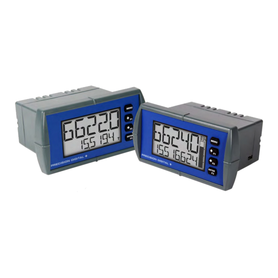
Loop Leader PD6620 Series Loop-Powered Rate/Totalizer
Instruction Manual
• 4-20 mA Input
• Loop-Powered Flow Rate/Totalizer
• 1.5 Volt Drop (4.7 Volt Drop with Backlight)
• Display Rate & Total Simultaneously
• Loop-Powered Backlight with Red Backlight for Alarm Conditions
• NEMA 4X, IP65 Front
• -40 to 167°F (-40 to 75°C) Safe Area Operating Temperature Range
• Free PC-Based USB Programming Software
• 5-Digit Alphanumeric Top Line
• 8-Digit Alphanumeric Bottom Line
• 8-Digit Total & Grand Total Display with 13 Digits Using Top Line
• 20-Segment Bargraph with Numeric Percent Indication
• Conformal Coated PCBs for Dust & Humidity Protection
• Two Open Collector Outputs Standard
• Dual-Line Display
• 1/8 DIN Shallow Depth Case
• Optional Loop-Powered Solid-State Relays
• Optional 4-20 mA Analog Output
• UL & C-UL 61010 Listed for Electrical Safety
• UL & C-UL Listed as Intrinsically Safe and Nonincendive
• ATEX and IECEx Certified as Intrinsically Safe
PRECISION DIGITAL CORPORATION
233 South Street • Hopkinton MA 01748 USA
Tel (800) 343-1001 • Fax (508) 655-8990
PD6626 & PD6628 Only
IECEx
Loop-Powered Totalizer
www.predig.com
Advertisement
Table of Contents
Troubleshooting

Related Manuals for PRECISION DIGITAL Loop Leader PD6620 Series


Summary of Contents for PRECISION DIGITAL Loop Leader PD6620 Series
- Page 1 Loop Leader PD6620 Series Loop-Powered Rate/Totalizer Instruction Manual PD6626 & PD6628 Only IECEx Loop-Powered Totalizer • 4-20 mA Input • Loop-Powered Flow Rate/Totalizer • 1.5 Volt Drop (4.7 Volt Drop with Backlight) • Display Rate & Total Simultaneously • Loop-Powered Backlight with Red Backlight for Alarm Conditions •...
- Page 2 Precision Digital Corporation warrants this product against defects in material or workmanship for the specified period under “Specifications” from the date of ship- ment from the factory. Precision Digital’s liability under this limited warranty shall not exceed the purchase value, repair, or replacement of the defective unit.
-
Page 3: Table Of Contents
Loop Leader PD6620 Series Loop-Powered Rate/Totalizer Instruction Manual Table of Contents Table of Contents ----------------------------------------- 3 Main Menu --------------------------------------------------------- 23 Setting Numeric Values -------------------------------------- 23 Table of Figures ------------------------------------------- 3 Setting Up the Input Signal (INPUT) ---------------------- 24 Introduction ------------------------------------------------- 4... -
Page 4: Introduction
Loop Leader PD6620 Series Loop-Powered Rate/Totalizer Instruction Manual Introduction These loop-powered 1/8 DIN flow rate/totalizers can be installed virtually anywhere to provide convenient and informative display of flow rate and total from a 4-20 mA signal. One of the most convenient features of these instruments is their ability to display both flow rate and total at the same time. -
Page 5: Ordering Information
Loop Leader PD6620 Series Loop-Powered Rate/Totalizer Instruction Manual Ordering Information General Purpose Instruments Loop Leader PD6622 • Standard Decimal Models – General Purpose Model Description PD6622–LNN Loop-Powered, General Purpose, No Options PD6622–L2N Loop-Powered, General Purpose, Two Solid State Relays PD6622–L3N Loop-Powered, General Purpose, 4-20 mA Analog Output PD6622–L5N... -
Page 6: Specifications
Loop Leader PD6620 Series Loop-Powered Rate/Totalizer Instruction Manual Specifications Except where noted all specifications apply to operation at +25°C. General Input Environmental Operating temperature range: Input 4-20 mA -40 to 75°C for safe area products Accuracy ±0.02% of span ±1 count, Square root and -40 to 70°C for hazardous area products... -
Page 7: Rate/Totalizer
Loop Leader PD6620 Series Loop-Powered Rate/Totalizer Instruction Manual Common Open Collector & Relay (Alarm) Specifications Rate/Totalizer Rate Display High or Low User programmable for high or low alarm Top display: -9999 to 99999; bottom display: Capability Alarm -9,999,999 to 99,999,999 (with commas) Total &... -
Page 8: Solid State Relays
Loop Leader PD6620 Series Loop-Powered Rate/Totalizer Instruction Manual Solid State Relays MeterView XL Programming Software Rating System Microsoft® Windows® 7 & 10 Resistive Load: 250 VAC/DC @ 1 A Requirements Inductive Load: 75 VA @ 0.6 A, 250 VAC/DC max (Safe Area only) Communications USB 2.0 (Standard USB A to Micro USB B) -
Page 9: General Compliance Information
Loop Leader PD6620 Series Loop-Powered Rate/Totalizer Instruction Manual General Compliance Information Electromagnetic Compatibility EMC Emissions • CFR 47 FCC Part 15 Subpart B Class A emissions requirements (USA) • AS/NZS CISPR 11:2004 Class A ISM emissions requirements (Australia) • EN 55011:2009/A1:2010 Group 1 Class A ISM emissions requirements (EU) •... - Page 10 Loop Leader PD6620 Series Loop-Powered Rate/Totalizer Instruction Manual ATEX/IECEx Special Conditions for Safe Use The following conditions relate to safe installation and/or use of the equipment. • The permitted ambient temperature range for the PD6606/PD6608 is -40°C to 70°C. • The equipment must be installed in an enclosure which provides a minimum degree of protection of IP20 for the equipment connections.
-
Page 11: Safety Information
Loop Leader PD6620 Series Loop-Powered Rate/Totalizer Instruction Manual Safety Information CAUTION: Read complete in- WARNING: Risk of electric structions prior to installation shock or personal injury. and operation of the meter. Warning! • Hazardous voltages exist within enclosure. Installation and service should be performed only by trained service personnel. -
Page 12: Panel Mounting Instructions
Loop Leader PD6620 Series Loop-Powered Rate/Totalizer Instruction Manual Panel Mounting Instructions Prepare a standard 1/8 DIN panel cutout – 3.622" x 1.772" (92 mm x 45 mm). Refer to Figure 1 be- • low, for more details. Clearance: allow at least 4.0" (102 mm) behind the panel for wiring. -
Page 13: Connections
Loop Leader PD6620 Series Loop-Powered Rate/Totalizer Instruction Manual Connections All connections are made to removable screw terminal connectors located at the rear of the meter. This section is only intended for PD6622 and PD6624 safe area installations. PD6626 and PD6628 installation must be performed in accordance with Control Drawing LIM6600-2 in order to meet agency approval ratings. -
Page 14: Safe Area Current Loop (4-20 Ma) Connections
Loop Leader PD6620 Series Loop-Powered Rate/Totalizer Instruction Manual Safe Area Current Loop (4-20 mA) Connections Signal connections are made to a six-terminal connector labeled SIGNAL on Figure 4. The following fig- ures show a 4-20 mA current loop connected to the meter. The first figure shows the connection without the backlight and the second shows the connection with the backlight (the backlight may also be disa- bled/enabled in the SYSTEM menu). -
Page 15: Safe Area 4-20 Ma Output Connections
Loop Leader PD6620 Series Loop-Powered Rate/Totalizer Instruction Manual Safe Area 4-20 mA Output Connections Connections for the 4-20 mA transmitter output are made to the connector terminals labeled mA OUT. The 4-20 mA output must be powered from an external power supply. -
Page 16: Safe Area Open Collector Outputs
Loop Leader PD6620 Series Loop-Powered Rate/Totalizer Instruction Manual Safe Area Open Collector Outputs Open collector output 1 and 2 connections are made to terminals labeled O1+ and O1-, and O2+ and O2-. Connect the alarm or pulse input device as shown below. -
Page 17: Setup And Programming
Loop Leader PD6620 Series Loop-Powered Rate/Totalizer Instruction Manual Setup and Programming The meter is factory calibrated prior to shipment to display 0 to 100, which corresponds to the 4-20 mA input. The calibration equipment is traceable to NIST standards. Overview There are no jumpers to set;... -
Page 18: Meterview Xl Programming Software
Loop Leader PD6620 Series Loop-Powered Rate/Totalizer Instruction Manual MeterView XL Programming Software The meter can also be programmed using PC-based MeterView XL software. This software greatly simpli- fies the programming process and also allows the user to save configuration files for later use. -
Page 19: Display Functions & Messages
Loop Leader PD6620 Series Loop-Powered Rate/Totalizer Instruction Manual Display Functions & Messages The meter displays various functions and messages during setup, programming, and operation. The following table shows the main menu functions and messages in the order they appear in the menu. - Page 20 Loop Leader PD6620 Series Loop-Powered Rate/Totalizer Instruction Manual Parameter Action/Setting Description Parameter Action/Setting Description Scale or calibrate the 4-20 mA in- Program the grand total reset SCALE. C AL GTOTAL password Scale the rate 4-20 mA input Assign function keys and digital in-...
- Page 21 Loop Leader PD6620 Series Loop-Powered Rate/Totalizer Instruction Manual Parameter Action/Setting Description Parameter Action/Setting Description Start a batch Enable the backlight (default) START ENABLE Stop a batch Disable the backlight STOP DISABLE Start or stop a batch View meter software, version, and...
- Page 22 Loop Leader PD6620 Series Loop-Powered Rate/Totalizer Instruction Manual Parameter Action/Setting Description Parameter Action/Setting Description Display the grand total Display the units GTOTAL UNITS Display the grand total and its Display the preset value GT+UNITS PRESET units alternating Display the stopwatch...
-
Page 23: Main Menu
Loop Leader PD6620 Series Loop-Powered Rate/Totalizer Instruction Manual Main Menu The main menu consists of all the meter’s programmable functions: Input, Output, Advanced, and Dis- play. Press Menu button to enter Pro- • Run Mode gramming Mode then press the 52. -
Page 24: Setting Up The Input Signal (Input)
Loop Leader PD6620 Series Loop-Powered Rate/Totalizer Instruction Manual Setting Up the Input Signal (INPUT) It is very important to read the following information before proceeding to program the meter: The meter is factory calibrated prior to shipment to display 0-100 gal/s, which corresponds to the 4-20 •... -
Page 25: Available Unit Classes And Units
Loop Leader PD6620 Series Loop-Powered Rate/Totalizer Instruction Manual Available Unit Classes and Units The meter has preprogrammed rate and time base units. The following are available units to choose from: Rate Time Bases (TIME) Rate Units (RATE) Units per second... -
Page 26: Setting The Display Features (Display)
Loop Leader PD6620 Series Loop-Powered Rate/Totalizer Instruction Manual Setting the Display Features (DISPLAY) The meter’s display functions may be programmed using the Display menu. This menu consists of the following submenus: Units, Decimal Point, Comma, Bargraph (PD6624/8 Only), Top, and Bottom. -
Page 27: Changing What Is Displayed (Top And Bottom)
Loop Leader PD6620 Series Loop-Powered Rate/Totalizer Instruction Manual Changing What is Displayed (TOP and BOTTOM) The two display lines (Top and Bottom) can be programmed to display different values. Use the Top and Bottom menus to make these changes. If PV2 is enabled, additional options will be available for display- ing the second PV on the bottom display. -
Page 28: Programming The Outputs (Output)
Loop Leader PD6620 Series Loop-Powered Rate/Totalizer Instruction Manual Programming the Outputs (OUTPUT) Depending on the purchased model, the meter may be available with two open collector outputs, two solid state relays, and one 4-20 mA output. The Output menu will only show options for the available out- puts. -
Page 29: Open Collector Outputs (Open Collectr)
Loop Leader PD6620 Series Loop-Powered Rate/Totalizer Instruction Manual Open Collector Outputs (OPEN COLLECTR) The meter is equipped with two NPN open collector outputs that may be set up for pulse outputs, alarms, timed pulses, total reset, or disabled. Pulse outputs can be set to transmit the rate, total, or grand total. Output 2 may be used to generate a quadrature output based on the other open collector output. - Page 30 Loop Leader PD6620 Series Loop-Powered Rate/Totalizer Instruction Manual Pulse (PULSE) Pulse outputs may be assigned to output the rate, total, or grand total at a programmable factor. If the output is assigned to rate, the factor is a multiplier that determines the number of pulses generated based on the rate.
- Page 31 Loop Leader PD6620 Series Loop-Powered Rate/Totalizer Instruction Manual Alarm (ALARM) Alarm outputs may be assigned to the rate, total, grand total, or the digital input. When assigned to the rate, the alarm may be set as either a high alarm or a low alarm. Alarm actions (AUTO, AUTO. M AN, LATCH, L-CLEAR) determine how and when the alarm should be reset.
- Page 32 Loop Leader PD6620 Series Loop-Powered Rate/Totalizer Instruction Manual Timer (TIMER) The timer output may be set to generate the timed pulse only once (ONESHOT) or continuously (CONT). The timer output produces a constant width pulse at a constant frequency, if set as continuous timer.
-
Page 33: Solid State Relay Outputs (Relay)
Loop Leader PD6620 Series Loop-Powered Rate/Totalizer Instruction Manual Solid State Relay Outputs (RELAY) The meter is optionally equipped with two solid state relays that may be set up for alarms, sample, timer, or batch control. Alternatively, they may be disabled. - Page 34 Loop Leader PD6620 Series Loop-Powered Rate/Totalizer Instruction Manual Alarm (ALARM) Alarm outputs may be assigned to the rate, total, or grand total values, or the digital input. When assigned to the rate, the alarm may be set as either a high alarm or a low alarm. Alarm actions (AUTO, AUTO. M AN, LATCH, L-CLEAR) determine how and when the alarm should be reset.
- Page 35 Loop Leader PD6620 Series Loop-Powered Rate/Totalizer Instruction Manual Sample (SAMPLE) A relay set to sample will trigger when the total or grand total value has incremented by a programmed amount. The relay can be programmed to stay on for a specified amount of time.
- Page 36 Loop Leader PD6620 Series Loop-Powered Rate/Totalizer Instruction Manual Batch Control (BATCH) Selecting batch control for relay 1 will enable batching features on the meter. The top display will be changed to show the total and the bottom display will be changed to display the preset batch amount. The function keys will be changed so that F1 starts a batch, F2 opens the preset menu to allow the preset value to be changed, and F3 stops the currently running batch.
- Page 37 Loop Leader PD6620 Series Loop-Powered Rate/Totalizer Instruction Manual Stopwatch (STPWATCH) The stopwatch function may be used to manually run and control a process for a specific time interval up to 99 hrs., 59 min, and 59 seconds. The stopwatch function may be assigned to any relay. There are three settings needed to use the function effectively.
-
Page 38: Ma Output (4-20 Ma)
Loop Leader PD6620 Series Loop-Powered Rate/Totalizer Instruction Manual 4-20 mA Output (4-20 mA) The 4-20 mA menu is used to scale the 4-20 mA output based on display values. This menu is not present on models without a 4-20 mA output option. -
Page 39: Advanced Features Menu (Advanced)
Loop Leader PD6620 Series Loop-Powered Rate/Totalizer Instruction Manual Advanced Features Menu (ADVANCED) To simplify the setup process, functions not needed for most applications are located in the Advanced Features menu. The options under advanced features include: advanced rate, total, and grand total setup, cutoff, filter, password, function key programming, and system settings. - Page 40 Loop Leader PD6620 Series Loop-Powered Rate/Totalizer Instruction Manual Signal Input Conditioning Functions (FUNCTION) The Function menu is used to select the signal input conditioner applied to the input: linear, square root, or programmable exponent calculation. Multi-point linearization is part of the linear function selection.
- Page 41 Loop Leader PD6620 Series Loop-Powered Rate/Totalizer Instruction Manual Advanced Scaling and Calibration (SCALE. C AL) This menu offers options to scale or calibrate the meter. Scaling the Input (SCALE) The scale menu in the Advanced menu is the same as the scale menu in the Input menu. See Setting Up the Input Signal (INPUT) on page 24 for details about scaling the meter.
-
Page 42: Low-Flow Cutoff (Cutoff)
Loop Leader PD6620 Series Loop-Powered Rate/Totalizer Instruction Manual Low-Flow Cutoff (CUTOFF) The low-flow cutoff feature allows the meter to be programmed so that the output from a flowmeter always displays zero on the meter at low flow rates. The cutoff value may be programmed from 0 to 999999.9. The meter will display zero below the cutoff value. -
Page 43: Programmable Function Keys User Menu (User)
Loop Leader PD6620 Series Loop-Powered Rate/Totalizer Instruction Manual Programmable Function Keys User Menu (USER) The User menu allows the user to assign the front panel function keys F1, F2, and F3, and the digital in- put (located on the signal input connector) to access some of the menus or to activate certain functions immediately (e.g. -
Page 44: Changing System Settings (System)
Loop Leader PD6620 Series Loop-Powered Rate/Totalizer Instruction Manual Enabling the Function Key Hint Feature (HINT) Enabling the function key hint feature will cause a hint message to be displayed when pressing the F1, F2, or F3 function keys. This text gives a brief description of what the button is programmed to do. Press- ing that function key a second time will execute that action. - Page 45 Loop Leader PD6620 Series Loop-Powered Rate/Totalizer Instruction Manual Calibrating the Internal mA Reference (ICAL) The meter is factory calibrated prior to shipment to display 0 to 100, which corresponds to the 4-20 mA input. The calibration equipment is traceable to NIST standards.
-
Page 46: Meter Operation
Loop Leader PD6620 Series Loop-Powered Rate/Totalizer Instruction Manual Meter Operation The meter is capable of accepting a 4-20 mA current signal and displaying it in engineering units from -9,999 to 99,999 on the top line or from -9,999,999 to 99,999,999 on the bottom line. For example, a 4-20 mA signal could be displayed as -50.00 to 50.00. -
Page 47: Troubleshooting
Loop Leader PD6620 Series Loop-Powered Rate/Totalizer Instruction Manual Troubleshooting Due to the many features and functions of the meter, it’s possible that the setup of the meter does not agree with what an operator expects to see. If the meter is not working as expected, refer to the recommendations below. -
Page 48: Factory Default Settings
Loop Leader PD6620 Series Loop-Powered Rate/Totalizer Instruction Manual Factory Default Settings The following table shows the factory setting for most of the programmable parameters on the meter. Parameter Display Default Setting Parameter Display Default Setting Batch Count Input Menu BATCH COUNT... -
Page 49: Troubleshooting Tips
Loop Leader PD6620 Series Loop-Powered Rate/Totalizer Instruction Manual Troubleshooting Tips Symptom Check/Action 1. Check that the 4-20 mA current loop is providing at least 3.5 mA to the meter. No display at all 2. Check that the voltage drop of all devices con- nected to the 4-20 mA current loop does not ex- ceed the max rating of the loop power supply. -
Page 50: Eu Declaration Of Conformity For Pd6622 & Pd6624
Loop Leader PD6620 Series Loop-Powered Rate/Totalizer Instruction Manual EU Declaration of Conformity for PD6622 & PD6624 Issued in accordance with ISO/IEC 17050-1:2004. Precision Digital Corporation 233 South Street Hopkinton, MA 01748 USA as the manufacturer, declare under our sole responsibility that the product(s),... -
Page 51: Eu Declaration Of Conformity For Pd6626 & Pd6628
Loop Leader PD6620 Series Loop-Powered Rate/Totalizer Instruction Manual EU Declaration of Conformity for PD6626 & PD6628 Issued in accordance with ISO/IEC 17050-1:2004 and ATEX Directive 2014/34/EU. Precision Digital Corporation 233 South Street Hopkinton, MA 01748 USA as the manufacturer, declare under our sole responsibility that the product(s),... - Page 52 Loop Leader PD6620 Series Loop-Powered Rate/Totalizer Instruction Manual How to Contact Precision Digital • For Technical Support please Call: (800) 610-5239 or (508) 655-7300 Fax: (508) 655-8990 Email: support@predig.com • For Sales Support or to place an order please contact your local distributor or...
Need help?
Do you have a question about the Loop Leader PD6620 Series and is the answer not in the manual?
Questions and answers