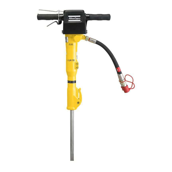
Atlas Copco LH 11 Manual
Handheld hydraulic breakers
Hide thumbs
Also See for LH 11:
- Safety and operating instructions manual (304 pages) ,
- Safety and operating instructions manual (28 pages)

Related Manuals for Atlas Copco LH 11


Summary of Contents for Atlas Copco LH 11
- Page 1 11, 18, 19 E, 22, 23 E, 27, 28 E, 39, 40 E Overhauling instructions Handheld hydraulic breakers © 2008 Atlas Copco Construction Tools AB No. 3392 5143 01 2008-02-29...
- Page 3 LH 11, 18, 19 E, 22, 23 E, 27, 28 E, 39, 40 E Contents Contents English ..............
-
Page 4: Table Of Contents
LH 11-LH 19 E ........ -
Page 5: About The Overhauling Instructions
LH 11, 18, 19 E, 22, 23 E, 27, 28 E, 39, 40 E Overhauling instructions About the Overhauling instructions The aim of the instructions is to provide you with knowledge of how to make basic overhauling of the LH 11-40 handheld hydraulic breakers. -
Page 6: Repair - General Information
Overhauling instructions LH 11, 18, 19 E, 22, 23 E, 27, 28 E, 39, 40 E special tools for repair repair - general information Before repairing the handheld hydraulic breakers, read the following in order to avoid incorrect repair and damage to the breaker. -
Page 7: Disassembly
LH 11, 18, 19 E, 22, 23 E, 27, 28 E, 39, 40 E Overhauling instructions Disassembly main components Remount the breaker in the vice Mount the breaker in a vice Hammer the nabs away from the screws Loosen the nose part (a torque wrench can... - Page 8 Overhauling instructions LH 11, 18, 19 E, 22, 23 E, 27, 28 E, 39, 40 E Remove the screws Remove the accumulator Remove the handle from the accumulator Remove the trigger valve Loosen the four screws on the accumulator Loosen the screws in the valve housing ©...
- Page 9 LH 11, 18, 19 E, 22, 23 E, 27, 28 E, 39, 40 E Overhauling instructions Remove the valve housing from the cylinder Remove the striking piston from the cylinder © 2008 Atlas Copco Construction Tools AB No. 3392 5143 01...
-
Page 10: Nose Part
Overhauling instructions LH 11, 18, 19 E, 22, 23 E, 27, 28 E, 39, 40 E nose part Remove the locking ring Mount the nose part in a vice Remove the chisel bellows Hammer out the two roll pins and remove... -
Page 11: Valve Housing
LH 11, 18, 19 E, 22, 23 E, 27, 28 E, 39, 40 E Overhauling instructions valve housing Remove the spool Mount the valve housing in a vice Loosen and remove the P guide socket Loosen and remove the T guide socket ©... -
Page 12: Trigger Valve
Overhauling instructions LH 11, 18, 19 E, 22, 23 E, 27, 28 E, 39, 40 E trigger valve Remove the Seeger spring ring Remove the packing gland from the trigger Remove the O-ring, the back-up ring and the Seeger spring ring from the trigger... -
Page 13: Accumulator
LH 11, 18, 19 E, 22, 23 E, 27, 28 E, 39, 40 E Overhauling instructions Accumulator Danger The breaker has a pressure accumulator. This accumulator is pressurized even when there is no hydraulic pressure to the breaker. Attempting to dismantle the accumulator without first releasing the pressure can cause personal injury or death. - Page 14 Overhauling instructions LH 11, 18, 19 E, 22, 23 E, 27, 28 E, 39, 40 E Remove the accumulator cover Remove the diaphragm Check the diaphragm for defects © 2008 Atlas Copco Construction Tools AB No. 3392 5143 01 2008-02-29...
-
Page 15: Cylinder
LH 11, 18, 19 E, 22, 23 E, 27, 28 E, 39, 40 E Overhauling instructions Cylinder Remove the locking ring Mount the cylinder in a vice Remove the seal and the back-up washer Remove the locking ring Remove the seal ©... -
Page 16: E-Handle
Overhauling instructions LH 11, 18, 19 E, 22, 23 E, 27, 28 E, 39, 40 E E-handle E-handle without top cover Hammer out the roll pin Puncture the rubber handles Remove the trigger lever Remove the rubber handles with compressed air (while pulling the handles) ©... - Page 17 LH 11, 18, 19 E, 22, 23 E, 27, 28 E, 39, 40 E Overhauling instructions Hammer out the two roll pins (with a punch) across from each other Hammer out the left and right latch pin with a punch. Remove and replace the trigger pawl...
- Page 18 Overhauling instructions LH 11, 18, 19 E, 22, 23 E, 27, 28 E, 39, 40 E Remove the eight nylon guides from the frame. Replace and grease the nylon guides when assembling Main parts of the E-handle note: The old E-handle with damping element...
-
Page 19: Assembly
LH 11, 18, 19 E, 22, 23 E, 27, 28 E, 39, 40 E Overhauling instructions Assembly valve housing LH 11-LH 19 E P and T guide sockets Parts to be used Mount the O-rings on the guide socket P and T location (written on housing) - Page 20 Overhauling instructions LH 11, 18, 19 E, 22, 23 E, 27, 28 E, 39, 40 E Incorrect mounting of the auxiliary spool Mount the P guide socket at the P side Oil the guide sockets Mount the spool at the T side (notice the...
- Page 21 LH 11, 18, 19 E, 22, 23 E, 27, 28 E, 39, 40 E Overhauling instructions Tighten the guide sockets with the torque wrench Check the movement of the spool by shaking it from side to side © 2008 Atlas Copco Construction Tools AB No.
-
Page 22: Valve Housing (New Type) Lh 22-Lh 40 E
Overhauling instructions LH 11, 18, 19 E, 22, 23 E, 27, 28 E, 39, 40 E valve housing (new type) LH 22-LH 40 E Mount the O-rings on the guide sockets Parts to be used P and T location (written on housing) - Page 23 LH 11, 18, 19 E, 22, 23 E, 27, 28 E, 39, 40 E Overhauling instructions Apply Loctite or similar to the guide socket thread Tighten the guide sockets with the torque wrench Mount the spool at the T side (notice the...
-
Page 24: Cylinder
Overhauling instructions LH 11, 18, 19 E, 22, 23 E, 27, 28 E, 39, 40 E Cylinder Mount the seal on a punch (see "Special tools for repair" Parts to be used Mount the seal with an engineer's hammer Mount the seal (green) -
Page 25: Accumulator
LH 11, 18, 19 E, 22, 23 E, 27, 28 E, 39, 40 E Overhauling instructions Accumulator Grease the accumulator cover with copper grease Parts to be used Mount the accumulator cover in the body Mount the diaphragm Oil the diaphragm where the cover seals on... - Page 26 Overhauling instructions LH 11, 18, 19 E, 22, 23 E, 27, 28 E, 39, 40 E Mount the charging screw and the seal ring Charge the accumulator with Nitrogen gas by means of filling device (part number 3371 8010 55).
-
Page 27: Main Components
LH 11, 18, 19 E, 22, 23 E, 27, 28 E, 39, 40 E Overhauling instructions main components Mount the O-rings Oil the seals in the cylinder Apply Loctite or similar to the cylinder thread Mount the striking piston in the cylinder... - Page 28 Overhauling instructions LH 11, 18, 19 E, 22, 23 E, 27, 28 E, 39, 40 E Mount the washers and the screws in the Check the movement of the striking piston valve housing using Loctite or similar in the valve housing...
- Page 29 LH 11, 18, 19 E, 22, 23 E, 27, 28 E, 39, 40 E Overhauling instructions Mount the trigger valve Tighten the screws on the accumulator: Apply Loctite or similar to the valve Mount the nose part housing threads Apply Loctite or similar to the screws Mount the accumulator ©...
- Page 30 Overhauling instructions LH 11, 18, 19 E, 22, 23 E, 27, 28 E, 39, 40 E Mount the screws on the nose part and tighten them © 2008 Atlas Copco Construction Tools AB No. 3392 5143 01 2008-02-29...
-
Page 31: Mounting Of Bushing In Nose Part
LH 11, 18, 19 E, 22, 23 E, 27, 28 E, 39, 40 E Overhauling instructions mounting of bushing in nose part Apply Loctite or similar to the bushing Mount the nose part in a hydraulic press designed for min. 10 t... -
Page 32: Mounting Of Latch In Nose Part
Overhauling instructions LH 11, 18, 19 E, 22, 23 E, 27, 28 E, 39, 40 E mounting of latch in nose part Place the nose part on an anvil Grease the lock pin and the spring with copper grease Hammer the bigger roll pin with the... - Page 33 LH 11, 18, 19 E, 22, 23 E, 27, 28 E, 39, 40 E Overhauling instructions It should look like this Check that the latch is moveable and that the spring and pin lock it in two positions © 2008 Atlas Copco Construction Tools AB No.
-
Page 34: Adjustment Of E-Handle
Overhauling instructions LH 11, 18, 19 E, 22, 23 E, 27, 28 E, 39, 40 E Adjustment of E-handle Mount the handle on the breaker Activate the trigger lever Adjust the trigger pawl to a clearance of 1-2 mm. The sliding surface should align with the breaker to keep the trigger from pulsating ©... - Page 36 Any unauthorized use or copying of the contents or any part thereof is prohibited. This applies in particular to trademarks, model denominations, part numbers and drawings. www.atlascopco.com...
Need help?
Do you have a question about the LH 11 and is the answer not in the manual?
Questions and answers