
Related Manuals for Retsch TM 300


Summary of Contents for Retsch TM 300
- Page 1 Manual Drum Mill TM 300 Translation © Retsch GmbH, 42781 Haan, Retsch-Allee 1-5, Germany | 05.04.2019 Version 0002...
- Page 2 Copyright © Copyright by Retsch GmbH Retsch-Allee 1-5 42781 Haan Germany...
-
Page 3: Table Of Contents
Table of Contents Notes on the Manual ..........................6 Disclaimer ............................6 Copyright............................6 Safety ..............................7 Explanations of the Safety Instructions ..................... 8 General Safety Instructions ....................... 9 Repairs ............................. 10 Responsibility of the operating company ..................11 Personnel qualification and target group of this manual ..............11 Confirmation Form for the Managing Operator................ - Page 4 5.8.3 Grinding position .......................... 38 5.8.4 Emptying position ........................39 5.8.5 Complete emptying position ......................39 Removing sample material after grinding ..................40 5.10 Accessories............................41 Control panel – Operating the machine .................... 42 Start menu ............................42 Settings ............................43 Starting the grinding process ......................
- Page 5 Notes on the Manual...
-
Page 6: Notes On The Manual
This Manual does not contain any repair instructions. Please contact your supplier or contact Retsch GmbH directly if anything is unclear or you have questions about these guidelines or the device, or in the case of any faults or necessary repairs. -
Page 7: Safety
All those operating, cleaning or working with or on the device. This device is a modern, powerful product from Retsch GmbH and has been developed in line with the state-of-the art. The device is safe to use when operated correctly and when following the instructions in this manual. -
Page 8: Explanations Of The Safety Instructions
Safety 2.1 Explanations of the Safety Instructions The following warnings in this Manual warn of possible risks and damage: DANGER D1.0000 Risk of fatal injuries Source of danger − Possible consequences if the danger is ignored. • Instructions and information on how to avoid the risk. Fatal or serious injuries may result if the “Danger”... -
Page 9: General Safety Instructions
− The conformity declared by Retsch GmbH with the European Directives will lose its validity. − Any warranty claims will be terminated. • Do not make any modification to the device. • Use spare parts and accessories that have been approved by Retsch GmbH exclusively. -
Page 10: Repairs
2.3 Repairs This manual does not contain any repair instructions. For safety reasons, repairs may only be carried out by Retsch GmbH or an authorised representative or by qualified service technicians. In case of repair, please inform… …the Retsch GmbH representative in your country, …your supplier, or... -
Page 11: Responsibility Of The Operating Company
Accepted, applicable rules governing occupational health and safety Incorporate the TM 300 into your emergency planning: • Integrate the TM 300 into your operating procedures regulating conduct in emergency situations. • To prevent accidents during work processes, incorporate the TM 300 into your risk assessment in acc. -
Page 12: Confirmation Form For The Managing Operator
Safety 2.6 Confirmation Form for the Managing Operator This manual contains essential instructions for operating and maintaining the device which must be strictly observed. It is essential that they be read by the user and by the qualified staff responsible for the device before the device is commissioned. This manual must be available and accessible at the place of use at all times. -
Page 13: Packaging, Transport And Installation
N5.0014 Complaints Incomplete delivery or transport damage − The forwarding agent and Retsch GmbH must be notified immediately in the event of transport damage. It is otherwise possible that subsequent complaints will not be recognised. • Please check the delivery on receipt of the device for its completeness and intactness. -
Page 14: Conditions For The Installation Site
Packaging, Transport and Installation 3.4 Conditions for the Installation Site − Installation height: max. 2 000 m above sea level − Ambient temperature: 5 °C – 40 °C NOTICE N7.0021 Ambient temperature Temperatures outside the permitted range − Electronic and mechanical components may be damaged. −... -
Page 15: Electrical Connection
Packaging, Transport and Installation 3.5 Electrical Connection WARNING W2.0015 Risk to life caused by an electric shock Connection to socket without a protective earth conductor − Connecting the device to sockets without a protective earth conductor can lead to life-threatening injuries caused by an electric shock. •... -
Page 16: Transport
Packaging, Transport and Installation 3.6 Transport WARNING W3.0005 Risk of injury due to the device falling down Lifting the device above head height − The device can fall causing serious injuries when lifted above head height. • Never lift the device above head height! NOTICE N10.0018 Transportation lock... -
Page 17: Installing The Device
Packaging, Transport and Installation 3.7 Installing the device • Place the machine on a firm surface. Further parameters can be found in the “Technical data” chapter. The machine must be secured prior to commissioning. 3.8 Position of the user The position of the operator for normal operation is in front of the housing door, at the height of the control panel and the emergency stop button. -
Page 18: Description Of Type Plate
Packaging, Transport and Installation 3.9 Description of type plate Fig. 2: Type plate 1 Device designation 2 Year of manufacture 3 Article number 4 Serial number 5 Manufacturer’s address 6 CE mark 7 Disposal sign 8 Barcode 9 Voltage 10 Supply frequency 11 Output 12 Current 13 Number of fuses... -
Page 19: Technical Data
Technical data Technical data 4.1 Intended use of the device CAUTION C4.0010 Risk of burns or poisoning Varying sample properties − The properties and therefore also the chemical reactivity of the sample can change during the grinding process and can cause burns or poisoning as a result. - Page 20 Due to its tough design, the TM 300 has proven to be extremely useful in the building materials sector (cement), in geology, minerology, metallurgy and in the environmental sector.
-
Page 21: Grinding Drum Nominal Volume
Technical data 4.2 Grinding drum nominal volume NOTICE N13.0000 Wear or damage to the grinding set Insufficient filling quantity − Increased wear or damage to the grinding set is possible when operating the grinding set with insufficient filling quantity. • The grinding set must always be filled to at least 40% of the nominal volume. -
Page 22: Rated Power
Technical data 4.5 Rated Power NOTICE N14.0066 Wear or damage to the machine Operating without grinding set and with overloading − Operating the machine without a grinding set, grinding media and sample can result in increased wear or damage to the machine. •... -
Page 23: Emissions
• Where necessary, use additional visual signals. 4.7.1 Noise levels Noise levels TM 300: Noise measurement in accordance with DIN 45635-31-01-KL3 The noise levels are mainly influenced by the machine speed, the material being ground and the grinding set. -
Page 24: Degree Of Protection
Technical data 4.8 Degree of Protection − IP 55 4.9 Protective Equipment The machine is fitted with a safety mechanism which prevents the machine being started in an unsafe state. • The machine can only be started when the housing door is closed. •... -
Page 25: Installation Drawing
Technical data 4.12 Installation drawing construction size... -
Page 26: Operating The Device
Operating the device Operating the device CAUTION C7.0006 Risk of injury Sample material that is harmful to health − Sample material that is harmful to health can injure people (illness, contamination). • Use suitable extraction systems with sample material that is harmful to health. -
Page 27: Views Of The Device
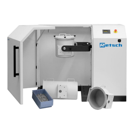
Operating the device 5.1 Views of the device Fig. 3: Front view of the machine... -
Page 28: Overview Table Of The Parts Of The Device
Operating the device 5.1.1 Overview table of the parts of the device Element Description Function Housing door Closes the grinding chamber. Prevents the housing door being closed if the rod module is not correctly positioned. Handle For opening the housing door . Emergency stop button Pressing this switches the machine off immediately. -
Page 29: Operating Elements And Displays
Operating the device 5.2 Operating elements and displays Fig. 4: View of the control panel 5.2.1 Overview Table of the Operating Elements and the Display Description Function Element Operating button For operating the machine settings. Button to open/lock the housing door Unlocks/locks the housing door . -
Page 30: Emergency Unlocking
Operating the device 5.5 Emergency Unlocking CAUTION C9.0009 Risk of injuries Drive coasting − In the event of a power failure, the drive on the device continues to coast for a long time, as does the drive on connected device parts. After activating the emergency release, items of clothing and parts of the body can get caught in moving components of the device. - Page 31 Operating the device Fig. 6: Emergency release procedure • Turn the key (SN) as far as it will go in a clockwise direction. • The interlock is open, and the hood can be opened. • The interlock must be set to “lock” again in order to be able to restart the machine. •...
-
Page 32: Inserting The Grinding Drum
Operating the device 5.6 Inserting the grinding drum NOTICE N15.0000 Wear or damage to the machine Operating without grinding module − Operating the machine without a grinding module can result in increased wear or damage to the machine. • Only operate the machine with an installed grinding module. 5.6.1 Grinding modules Fig. - Page 33 Operating the device Fig. 9: 21.7 litre ball module Fig. 10: 43.4 litre rod module...
-
Page 34: Preparing The Grinding Process
Operating the device 5.7 Preparing the grinding process 5.7.1 Filling the grinding balls Load the grinding drum with grinding balls • First fill the balls into the grinding drum, followed by the material. Fig. 11: Positioning the grinding balls 5.7.2 Filling the rods Load the grinding drum with grinding rods •... -
Page 35: Locking The Grinding Drum
Operating the device 5.7.3 Locking the grinding drum CAUTION C10.0024 Risk of burns and scalding Hot grinding drum and/or sample material − The sample material and grinding drum can get very hot during grinding. • Always wear protective gloves when touching the grinding drum after grinding. -
Page 36: Changing The Grinding Drum-Positions
Operating the device 5.7.4 Changing the grinding drum-positions Fig. 14: Image of the filling position • Unscrew the locking screw (I) and change the position of the grinding drum to the grinding position. -
Page 37: Grinding Drum Positions
Operating the device 5.8 Grinding drum positions CAUTION C11.0032 Risk of crushing Movement of the grinding drum − There is a risk of crushing caused by the turning and swinging of the grinding drum. • Turn the grinding drum carefully and make sure that your fingers do not get trapped in the supports while turning the drum. -
Page 38: Mixing Position
Operating the device 5.8.2 Mixing position Fig. 16: Grinding drum in the mixing position • Mixing is only possible with grinding drum sizes of up to 21.7 litres 5.8.3 Grinding position Fig. 17: Grinding drum in the grinding position... -
Page 39: Emptying Position
Operating the device 5.8.4 Emptying position Fig. 18: Grinding drum in the emptying position 5.8.5 Complete emptying position Fig. 19: Grinding drum in the complete emptying position... -
Page 40: Removing Sample Material After Grinding
Operating the device 5.9 Removing sample material after grinding CAUTION C12.0024 Risk of burns and scalding Hot grinding drum and/or sample material − The sample material and grinding drum can get very hot during grinding. • Always wear protective gloves when touching the grinding drum after grinding. -
Page 41: Accessories
Operating the device 5.10 Accessories The TM 300 is supplied with a suitable collecting receptacle and separation screen . This includes sieves to suit all ball sizes for separating the grinding balls from the material. Use a sieve with slightly smaller holes than the diameter of the balls used. The balls will otherwise also be sifted out. -
Page 42: Control Panel - Operating The Machine
Control panel – Operating the machine Control panel – Operating the machine 6.1 Start menu Press any function button. Fig. 22: Start menu – Housing door not locked Fig. 23: Start menu – Housing door locked F1: Start/Stop Starts and stops the machine. No function in the start menu. -
Page 43: Settings
Control panel – Operating the machine 6.2 Settings Select button F4 to go to the menu settings . Grinding can be configured using this menu. The display then shows the following functions: Fig. 24: Settings selection menu 1/5 Runtime (duration of the grinding process) F1: +1 Increases the duration of the grinding process. - Page 44 Control panel – Operating the machine Fig. 25: Settings selection menu 2/5 Fig. 26: Settings selection menu 2/5 In this menu you can specify the desired number of revolutions per minute to be made by the grinding drum. Speed (number of revolutions of the grinding drum) F1: +1 Increases the speed.
- Page 45 Control panel – Operating the machine The following setting appears after pressing button F4: Fig. 27: Settings selection menu 3/5 In this menu you can specify the desired interval duration for the grinding process. Interval duration F1: +1 Increases the interval duration. F2: -1 Decreases the interval duration.
- Page 46 Control panel – Operating the machine The following setting appears after pressing button F4: Fig. 28: Settings selection menu4/5 In this menu you can specify the desired duration of breaks between the intervals. This is only possible if you have previously selected interval mode. Break duration (duration of breaks between the intervals) F1: +1 Increases the break duration.
- Page 47 Control panel – Operating the machine The following setting appears after pressing button F4: Fig. 29: Settings selection menu5/5 In this menu you can specify the desired time for a delayed start of the grinding process. Start delay F1: +1 Increases the time until the start of grinding.
-
Page 48: Starting The Grinding Process
Control panel – Operating the machine 6.3 Starting the grinding process The display initially shows the following view once grinding has been started by pressing button Fig. 31: Display after starting grinding with start delay Confirm the safety question using button F1 if the grinding drum is in the horizontal position. Grinding will then start. - Page 49 Control panel – Operating the machine Fig. 33: Display during the grinding process 1 The display provides information about the current grinding process: Speed (In revolutions per Provides information about the current speed of the minute) grinding module. Torque (In percent) Provides information about the current torque of the grinding module.
-
Page 50: Information Notes
Control panel – Operating the machine 6.4 Information Notes The display shows this note once a grinding process has been stopped or is finished. Fig. 34: Note - Positioning The display provides information that the grinding drum is being placed in the correct position. Wait for the correct positioning of the grinding drum before opening the housing door and removing the sample material. -
Page 51: Error Messages
Control panel – Operating the machine 6.5 Error Messages An error message appears on the display if it is not possible to start the grinding process. The display shows the following error message if the emergency stop is activated or the housing door cannot be locked: Fig. -
Page 52: Maintenance
Maintenance Maintenance WARNING W4.0003 Risk to life caused by an electric shock Cleaning live parts with water − Cleaning the device with water can lead to life-threatening injuries caused by an electric shock if the device has not been disconnected from the power supply. -
Page 53: Removing The Side Cover
Maintenance 7.1 Removing the side cover Fig. 36: Side cover Fig. 37: Key • Release the locks marked on the image with the help of the supplied key . • Disconnect the earth cable on the inside of the cover. •... -
Page 54: Lubrication
Maintenance 7.2 Lubrication Fig. 38: Lubrication points Drive shaft The drive of the TM 300 has 2 lubrication points (SP) behind the side cover; these must be regularly lubricated after 150 hours of operation. Use a lithium based grease (without graphite) such as Shell Gadus S2 V220 2 or BP... -
Page 55: Return For Service And Maintenance
When returning a device, attach the return form to the outside of the packaging. In order to eliminate any health risk to the service technicians, Retsch GmbH reserves the right to refuse the acceptance and to return the respective delivery at the expense of the sender. -
Page 56: Disposal
Disposal Disposal In the case of a disposal, the respective statutory requirements must be observed. In the following, information on the disposal of electrical and electronic devices in the European Community are given. Within the European Community the disposal of electrically operated devices is regulated by national provisions that are based on the EU Directive 2012/19/EU on Waste Electrical and Electronic Equipment (WEEE). -
Page 57: Index
Index Index ‘ Emptying position ..........39 Error messages ..........51 ‘ 24 Explanations of the safety instructions ....8 External fuse ............15 Accessories ............41 All current sensitive ..........15 Feed size ............21 Ambient temperature .......... 14 maximum ............ - Page 58 Index Repair instructions ..........10 Required floor space .......... 24 Locking holes ............28 Residual current device ........15 Locking screw ............. 28 Responsibility of the operating company ... 11 Locking the grinding drum ........35 Return ..............13 Long-term operation ........... 19 for service and maintenance ......
- Page 59 Index Workplace-related emissions value ....23 Year of manufacture .......... 18...
- Page 62 Copyright © Copyright by Retsch GmbH Retsch-Allee 1-5 42781 Haan Germany...
Need help?
Do you have a question about the TM 300 and is the answer not in the manual?
Questions and answers