
Subscribe to Our Youtube Channel
Related Manuals for Retsch PM400


Summary of Contents for Retsch PM400
- Page 1 Manual Planetary Ball Mill PM400 Translation © Retsch GmbH, 42781 Haan, Retsch-Allee 1-5, Germany 26.03.2015 0001...
- Page 2 Copyright © Copyright by Retsch GmbH Haan, Retsch-Allee 1-5 D-42781 Haan Federal Republic of Germany...
-
Page 4: Table Of Contents
Notes on the Operating Manual ......................7 Explanations of the safety warnings ....................8 General safety instructions ........................ 9 Repairs ............................. 10 Confirmation ............................11 Transport, scope of delivery, installation ..................12 Packaging ............................12 Transport............................12 Temperature fluctuations and condensed water ................12 Conditions for the place of installation ..................... - Page 5 5.11 Power failure during grinding ......................33 5.12 Mahlbehälterauswahl für unterschiedlichen Probenmaterialien ............33 5.13 Sample quantity ..........................33 5.13.1 Guides for material quantity and balls ..................34 5.14 Ultrafine grinding ..........................34 5.15 Stacking the grinding jars ........................ 34 5.15.1 Stacking 50ml grinding jars ......................
- Page 6 6.8.7.2 Software version of display ....................45 6.8.7.3 Software version of the controller ..................45 6.8.7.4 Update software ........................45 6.8.7.4.1 Display ........................... 45 6.8.7.4.2 Controller ........................46 6.8.8 Safety notice ..........................46 Fault messages ............................. 47 Cleaning, wear and service ......................... 48 Service ..............................
-
Page 7: Notes On The Operating Manual
This operating manual does not contain any repair instructions. If faults arise or repairs are necessary, please contact your supplier or get in touch with Retsch GmbH directly. -
Page 8: Explanations Of The Safety Warnings
Notes on the Operating Manual 1.1 Explanations of the safety warnings In this Operating Manual we give you the following safety warnings Serious injury may result from failing to heed these safety warnings. We give you the following warnings and corresponding content. WARNING Type of danger / personal injury Source of danger... -
Page 9: General Safety Instructions
Target group : All persons concerned with the machine in any form This machine is a modern, high performance product from Retsch GmbH and complies with the state of the art. Operational safety is given if the machine is handled for the intended purpose and attention is given to this technical documentation. -
Page 10: Repairs
Reperatur en 1.3 Repairs This operating manual does not contain any repair instructions. For your own safety, repairs may only be carried out by Retsch GmbH or an authorized representative or by Retsch service engineers. In that case please inform:... -
Page 11: Confirmation
Confirmation Bes tätigung 2 Confirmation This operating manual contains essential instructions for operating and maintaining the device which must be strictly observed. It is essential that they be read by the operator and by the qualified staff responsible for the device before the device is commissioned. -
Page 12: Transport, Scope Of Delivery, Installation
NOTICE H0014 Complaints – The forwarding agent and Retsch GmbH must be notified immediately in the event of transport damage. It is otherwise possible that subsequent complaints will not be recognised. • Notify your forwarding agent and Retsch GmbH within 24h 3.3 Temperature fluctuations and condensed water... -
Page 13: Installation Of The Machine
Transport, scope of delivery, installation NOTICE Ambient temperature – Electronic and mechanical components may be damaged and the performance data alter to an unknown extent. • Do not exceed or fall below the permitted temperature range of the machine (5°C to 40°C / ambient temperature). 3.5 Installation of the machine Installation height: maximum 2000 m above sea level 3.6 Type plate description... -
Page 14: Creating Interface Connection
Transport, scope of delivery, installation When connecting the power cable to the mains supply, use an external fusethat complies with the regulations applicable to the place of installation . • Please check the type plate for details on the necessary voltage and frequency for the device. -
Page 15: Transport
Transport, scope of delivery, installation 3.9 Transport WARNING Serious personal injury Falling loads – The appliance is very heavy and can therefore cause serious personal injuries if it falls down. • Lifting above head height is not permissible! NOTICE Transport –... - Page 16 Transport, scope of delivery, installation Fig. 3: Removing the transport lock from the device Four bolts secure the transport lock underneath the device. • Use a 13mm spanner to unscrew the four bolts. Fig. 4: Mounting the transport screws The device should only be lifted and transported using the 4 transport screws (TS) provided.
-
Page 17: Installation Of The Machine
Transport, scope of delivery, installation 31.5 inches 31.5 inches Fig. 5: Attaching the hoist 3.10 Installation of the machine Fig. 6: Locking the transport rollers • Place the device on a firm surface. Please refer to the “Technical Data” chapter for further parameters. The device must be locked before it is put into operation. - Page 18 Transport, scope of delivery, installation NOTE Installation – Depending on the operating status of the mill, there may be slight vibrations. • Place the mill on an even, flat and balanced supporting surface only. The supporting surface must be stable and must not vibrate. NOTICE Installation of the machine –...
-
Page 19: Technical Data
Target group: Operating companies, operators Machine type designation: PM400 Retsch ball mills are used to grind and mix soft, medium hard and extremely hard, brittle and fibrous materials. Dry and wet grinding are possible. Minerals, ores, alloys, chemicals, glass, ceramics, parts of plants, soil, sewage sludge, house or industrial waste and many other substances can be ground simply, quickly and without loss. -
Page 20: Number Of Grinding Stations
Technical data 4.2 Number of grinding stations 2 or 4 depending on the model The grinding stations must be operated with the identical grinding jars and with the same weight during each grinding process. NOTICE H0068 Strong vibration and loud noise Uneven load –... -
Page 21: Emissions
4.10 Dimensions and weight Height: up to approx. 1220 mm / Width: 836 mm / Depth:up to approx. 780 mm Weight : PM400 net approx. 290 kg 4.11 Required floor space Height (open cover): 1900mm / Width: 1400mm / Depth: 900mm;... -
Page 22: Operating The Machine
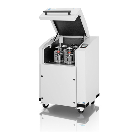
Operating the machine 5 Operating the machine 5.1 Views of the Instrument Fig. 7: View of the front of the device Fig. 8: Close-up of the grinding chamber... - Page 23 Operating the machine Fig. 9: View of the back of the device...
-
Page 24: Overview Table Of The Parts Of The Device
Operating the machine 5.2 Overview table of the parts of the device Element Description Function Cover Closes the grinding chamber Damper for cover Secures the cover when it is open Clamping unit for grinding chamber Clamps grinding jar on the support Grinding jar Sample vessel Turntable... -
Page 25: Operating Elements And Displays
Operating the machine 5.3 Operating elements and displays Fig. 10: View of the control panel 5.4 Overview Table of the Operating Elements and the Display Element Description Function Control knob (rotary/push button) Rotary control to operate the device settings Button to open the cover Unlocks the cover Display Displays the control functions and parameters... -
Page 26: Emergency Unlocking
Operating the machine 5.7 Emergency unlocking CAUTION Emergency Unlocking Drive continuing to run – There is a substantial risk of injury if the drive and associated device parts run on a long time without being braked! • Activate the emergency unlocking only when the machine has come to a complete stop and is disconnected from the power supply. -
Page 27: Inserting The Grinding Jar
Operating the machine Fig. 12: Emergency release procedure • At the same time as pushing the key (SN) in, rotate it in a clockwise direction as far as it will go. – The lock is open and the lid can be lifted up. 5.8 Inserting the grinding jar CAUTION V0049... -
Page 28: Clamping Bolt
Operating the machine 5.8.1 Clamping bolt Fig. 13: Correct loading of the device – 4 or 2 grinding jars Fig. 14: Incorrect loading of the device... - Page 29 Operating the machine Fig. 15: Clamping bolt When grinding with 2 grinding jars these must be inserted so they are opposite each other. The two remaining empty grinding stations must each be secured by a clamping bolt (Sb) and a clamping unit. Otherwise the safety slider function will stop the device from starting.
-
Page 30: Inserting The Grinding Jar
Operating the machine – The insertion and clamping of the clamping unit pushes the Safety Slider (O) upwards, thereby activating it. After the machine has started, the device checks this safety function for approx. 15 seconds. The device aborts the starting process and emits an error message if –... -
Page 31: Inserting The Clamping Unit
Operating the machine 5.8.3 Inserting the clamping unit Fig. 18: Inserting the clamping unit • Insert the clamping unit (H) in the three latching brackets (Q). 5.8.4 Function of the locking sleeve open blocked Fig. 19: Function of the locking sleeve •... -
Page 32: Releasing The Grinding Jar Clamping Mechanism
Operating the machine 5.9 Releasing the grinding jar clamping mechanism Fig. 20: Releasing the grinding jar clamping mechanism • Pull the red sleeve (5) upwards. • Turn the three-star grip to the left to release the grinding jar. • Keep turning the three-star grip to the left until the grinding jar clamping mechanism can be removed. -
Page 33: Power Failure During Grinding
The process is aborted by pressing the STOP button. 5.12 Mahlbehälterauswahl für unterschiedlichen Probenmaterialien This device is only suitable for use with grinding jars from Retsch GmbH with a nominal volume of 12 ml - 500 ml. They are available in the following materials: •... -
Page 34: Guides For Material Quantity And Balls
Operating the machine 5.13.1 Guides for material quantity and balls Grinding jar Sample Max. feed size Ball filling (unit) volume volume 10mm 20mm 30mm 40mm 12 ml Up to 5 ml 1 mm 5 units 25 ml Up to 10 ml 1 mm 8 units... -
Page 35: Stacking Grinding Jars Smaller Than 50Ml
5.16.2 Anti-rotation device All 250ml and 500ml grinding jars have a drilled hole underneath the grinding jar as anti-rotation device. The anti-rotation device is only used with the PM400 and is located on the side of the grinding jar casing with lettering. -
Page 36: Grinding Jar - Identification
Operating the machine When grinding jars have been left to cool, a vacuum is created inside them which can make them difficult to open. The grinding jars can be prised open between the gripping flanges on the lid and the grinding jar, e.g. using a flat wooden stick (Hb). 5.17 Grinding jar –... -
Page 37: Closing The Grinding Jar
Operating the machine Stainless steel Up to 200°C Tungsten carbide (TC) Up to 150°C Sintered corundum Up to 120°C Agate Up to 120°C Zirconium oxide Up to 120°C Silicon nitride Up to 120°C 5.19 Closing the grinding jar After filling the grinding jars, they should be closed using the locking mechanisms available as an accessory. - Page 38 Operating the machine The PM400 is fitted with a fan which extracts the waste heat created during grinding directly out of the grinding chamber. The extraction volume per hour is greater than 20 times the grinding chamber volume. The fan has standstill monitoring with signalling.
-
Page 39: Display And Operation
Display and operation 6 Display and operation 6.1 Symbols in the Display Unit Fig. 28: View of the menu on the display unit Element Description Function Menu navigation Switching between manual operating mode, program and basic settings Specification of grinding Displaying and setting grinding parameters parameters Icons for device functions... -
Page 40: Display Unit - Operation Of The Device
Display and operation Only scrolling downwards possible 6.2 Display unit – operation of the device This device offers a new, very convenient user inteface. All relevant data can be entered and retrieved using a graphics display with one-button operation. The menu is available in different languages. - Page 41 Display and operation • Switch the device off at the main switch. • Switch the device on while simultaneously pressing the buttons START - STOP – Open hood. • After selecting the correct language, switch the device off and then immediately back on.
-
Page 42: Menu Structure
Display and operation 6.4 Menu structure Complete summary of all menu options: MANUAL OPERATING MODE Grinding time BASIC SETTINGS Speed Automatic opening Interval Language Direction reversal Brightness Pause time Date Save parameters Time Program Acoustic signal Save Service Back Operating hours Start in Software version of display Start in:... -
Page 43: Manual Operation
Display and operation – Automatic opening – Language – Brightness – Date – Time – Acoustic warning signal – Service 6.6 Manual operation 6.6.1 Grinding time 00:01:59 to 99:59:59 (hours : minutes : seconds) The device is started with the preselected grinding time and at the last speed used. Direction reversal with pause time has not been switched on 6.6.2 Speed... -
Page 44: Start In
Display and operation Save to save settings or Back to cancel without saving. 6.6.7 Start in 00:00:01 to 99:59:59 (hours : minutes : seconds) You can set a countdown for starting the device. • Press the STOP button to cancel the countdown. 6.7 Programs 6.7.1 Change program... -
Page 45: Automatic Opening
Display and operation 6.8.1 Automatic opening In this menu you can set whether the grinding jar lid opens automatically when grinding ends or only when the button is pressed. If the function is switched off, the following pictogram appears on the display as confirmation. -
Page 46: Controller
Display and operation – The data are transmitted from the connected PC to the controller circuit board using an interface cable (RS232). The controller circuit board forwards the data to the boot loader of the display unit. 6.8.7.4.2 Controller – The target device controller is selected on the PC using a selection menu for updating software. -
Page 47: Fault Messages
Fault messages 7 Fault messages Error code (FEHLER) BESCHREIBUNG DEFECT DESCRIPTION TRANSLATION ANTRIEB ÜBERLASTET DRIVE OVERLOAD FEHLER ANTRIEB/MOTOR FAILURE DRIVE/MOTOR FEHLER STEUERUNG FAILURE CONTROLLER FEHELR LÜFTER FAILURE FAN FEHLER FREQUENZUMRICHTER FAILURE FREQUENCY CONVERTER FEHLER DREHZAHLSENSOR FAILURE SPEED SENSOR FEHLER SICHERHEITSKREIS FAILURE IN SAFETY CIRCUIT ANTRIEB ABKÜHLEN LASSEN! ALLOW DRIVE TO COOL DOWN... -
Page 48: Cleaning, Wear And Service
Cleaning, wear and service 8 Cleaning, wear and service WARNING Risk of a fatal electric shock An electric shock can cause injuries in the form of burns and cardiac arrhythmia, respiratory arrest or cardiac arrest. • Do not clean the blender under running water. Use only a cloth dampened with water. -
Page 49: Servicing The Clamping Unit
Cleaning, wear and service 8.1.1 Servicing the clamping unit Fig. 31: Servicing the clamping unit • Check that the threaded spindle (Gs) and locking sleeve (N1) can move freely. – In most cases a drop of oil will help. The smooth running of the threaded spindle and locking sleeve is the prerequisite for the secure clamping of the grinding jars. -
Page 50: Rubber Washer On The Pressure Plate
Cleaning, wear and service 8.1.3 Rubber washer on the pressure plate Fig. 33: Rubber washer on the pressure plate • Check the O-ring (Or) on the pressure plate regularly for wear and to ensure it is secure. 8.1.4 Wear to latching bracket H1: at least 15mm Fig. -
Page 51: Returning For Service And Maintenance
Cleaning, wear and service • Remove the mains cable before replacing fuses. Fig. 35: Changing the fuses NOTICE Always replace all 4 fuses (TB). – Type of fuse: 4 x 200mA T 250V • Unscrew the 4 fuse holders (TC). •... - Page 52 Cleaning, wear and service RETSCH devices and accessories can only be accepted for repair, maintenance or calibration if the returned goods despatch note has been correctly completed in full. • When returning a device, attach the returned goods dispatch note to the outside of the packaging.
-
Page 53: Disposal
Disposal 9 Disposal Please observe the respective statutory requirements with respect to disposal. Information on disposal of electrical and electronic machines in the European Community. Within the European Community the disposal of electrically operated devices is regulated by national provisions that are based on the EU Directive 2002/96/EC on Waste Electrical and Electronic Equipment (WEEE). -
Page 54: Index
10 Index > >Mains connection 14 Date 45 Degree of protection 21 Delete program 44 16A 20 Depth 21 Description 24, 25, 39 Device Acoustic warning signal 45 closing 25 Adjustment options using the display menu 40 open 25 Agate 33 Device designation 13 all current sensitive 14 Dimensions and weight 21... - Page 55 Hoist Power failure during grinding 33 attaching 17 Power version 13 Pressure plate 50 Probenmaterialien 33 Program 01 to 10 42 Inserting the clamping unit 31 Programs 44 Inserting the grinding jar 27, 30 property damage 8 Installation height 13, 17 Installation of the machine 13, 17 Protective earth 14 Protective equipment 21...
- Page 56 Use of the machine for the intended purpose 19 Target group 19 Target group 9 View of the back of the device 23 Technical data 19 View of the control panel 25 Temperature fluctuation and condensed water 12 View of the front of the device 22 Time 45 View of the menu on the display unit 39 Transport 12, 15...
- Page 57 Authorized person for the compilation of technical documents: Dr. Loredana Di Labio (technical documentation) The following records are held by Retsch GmbH in the form of Technical Documentation: Detailed records of engineering development, construction plans, study (analysis) of the measures required for conformity assurance, analysis of the residual risks involved and operating instructions in due form according to the approved regulations for preparation of user information data.
- Page 60 Copyright ® Copyright by Retsch GmbH Haan, Retsch-Allee 1-5 D-42781 Haan Federal Republic of Germany...
Need help?
Do you have a question about the PM400 and is the answer not in the manual?
Questions and answers