
Related Manuals for Rice Lake SCT-1100


Summarization of Contents
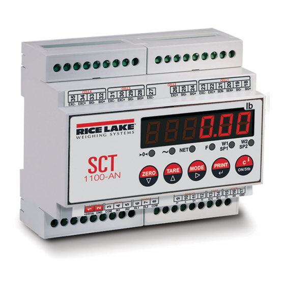
Introduction to the SCT-1100
Safety Signal Definitions
Defines DANGER, WARNING, CAUTION, and IMPORTANT signals for safety.
General Safety Precautions
Essential safety precautions for operating and maintaining the instrument.
1.2 Product Options
Lists the available features and optional capabilities of the SCT-1100.
1.3 Indicator Overview
Provides an overview of the indicator's physical dimensions and components.
1.3.1 Panel Display Components
Details the front panel components like display, LEDs, and keypad functions.
2.0 Installation Guide
2.1 Location Selection Criteria
Guidelines for choosing an appropriate location for the equipment.
2.2 Electrical Precautionary Measures
Important electrical safety precautions for installation.
2.3 Maximum Cable Lengths
Specifies maximum allowed cable lengths for various connections.
2.4 System Grounding
Procedures for properly grounding the instrument and system components.
2.4.1 Load Cells and Junction Box Grounding
Specific grounding instructions for load cells and junction boxes.
2.5 Wiring Schematic Diagram
Provides a detailed wiring diagram for the SCT-1100.
2.6 Load Cell Connection
Instructions on how to connect load cells to the instrument.
2.6.1 Input/Output Wiring Guide
Describes the wiring for the digital inputs and outputs.
3.0 Operation Procedures
3.1 Basic Operation
How to turn the instrument on, standby, and power off.
3.1.1 Powering On the Instrument
Procedure for powering on the instrument and initial checks.
3.1.2 Standby Mode Activation
How to put the instrument into standby mode.
3.1.3 Powering Off the Instrument
Procedure for completely powering off the unit.
3.1.4 Zeroing the Weight
How to zero the instrument's weight reading.
3.1.5 Tare Operation Guide
Instructions for performing tare operations.
3.2 Multi-Range Functionality
3.3 Display Configuration Data Access
How to view configured data like capacity and division.
3.4 Selecting Display Channel
How to select which scale channel to display.
3.5 Simultaneous Transmitter Mode
3.6 Printing Function Setup
How to configure printing options.
3.7 Operating Mode Selection
3.7.1 Conversion Functionality
Function for converting displayed weight units.
3.7.2 Alibi Memory Usage
Information about storing weight values for data processing.
3.7.3 Sensitivity Times Ten Testing
Mode for testing sensitivity during calibration.
3.7.4 Peak Hold Weight Detection
Feature to store the maximum measured weight.
4.0 Setup Mode Overview
4.1 Setup Mode Navigation Keys
Explains how to navigate through the setup menus using keys.
4.2 Quick Setup Menu
4.2.1 Default Factory Calibration Settings
Default calibration settings provided by the factory.
4.2.2 Quick Scale Setup Procedure
Procedure for setting up the scale using the quick setup menu.
4.2.3 Analog Output Configuration
Reference to analog output settings.
4.2.4 Input Configuration Reference
Reference to input setup parameters.
4.2.5 Output Functions Configuration
Reference to output function settings.
4.3 Setup Mode Menu Structure
4.3.1 Type Parameters Selection
Parameters to select the application type (independent/dependent channels).
4.3.2 F.Mode Parameters Functionality
Parameters that set the scale's functionality, printing, taring, and zeroing.
4.4.1 Filter Parameters Explained
Details on digital filters for noise compensation.
4.5 Input/Output Functions
4.5.1 Input Functions Configuration
Sets the function of each input.
4.5.2 Output Functions Definition
Defines the functionality of each output.
4.6 Analog Output Configuration
Calibrating Analog Output
Procedure for calibrating the analog output module.
5.0 Calibration Procedures
5.1.1 Calibration Parameters Explained
Lists and describes all available calibration parameters.
5.2 Scale Setup Procedure
Step-by-step procedure for setting up the scale during calibration.
5.3 Single Channel Calibration
Procedure for calibrating a single channel with known weight.
5.4 Multi Channel Calibration
Procedure for calibrating multiple channels with known weight.
5.5 Calibration With Linearization Points
5.5.1 Dependent Channels Calibration
Calibration with linearization points for dependent channels.
5.5.2 Independent Channels Calibration
Calibration with linearization points for independent channels.
5.6.1 Independent Channels Theoretical Calibration
Theoretical calibration for independent channels.
5.6.2 Dependent Channels Theoretical Calibration
5.7 Gravity Setting Correction
Correcting weight errors due to gravitational differences.
5.8 Zero Dead Load A/D Counts
Ideal A/D counts for zero dead load conditions.
6.0 Communications Overview
6.1.1 COM1 Serial Port Configuration
Configuration and use of the COM1 RS-485 serial port.
6.1.2 COM2 Serial Port Configuration
Configuration and use of the COM2 RS-232 serial port.
6.2 Serial Port Transmission Modes
6.2.1 PC Port Selection
Selecting which serial port to use for PC communication.
6.2.2 PRN PORT Settings
Settings for the printer port transmission.
6.2.3 PC PORT Settings
Settings for the PC serial port transmission modes.
6.3 Serial Commands Format
Serial Errors and Status Responses
Explains status responses and error codes for serial commands.
Weight Read Commands
Commands for reading weight data and related information.
Serial Command Reference
Tare, Zero, and Clear Commands
Commands for tare, zero, and clear operations.
Converter Channel and Print Commands
Commands for channel switching and printing.
Instrument Status and Message Commands
Display Message Commands
Commands for displaying temporary messages and setting intervals.
Instrument Status Command
Command to retrieve the current status of the instrument.
Key Press and Scale Information Commands
Key Press Simulation Commands
Commands to simulate key presses on the instrument.
Scale Information Reading Command
Command to read detailed scale information.
Setpoint and Keyboard Control Commands
Setpoint Commands
Commands for setting and saving setpoints on the instrument.
Keyboard Enable/Disable Command
Commands to enable or disable the instrument's keyboard.
6.4 Transmission Protocols
6.4.1 Standard String Format
Describes the standard format for transmitting weight data.
6.4.2 Extended String Format
Describes the extended format for transmitting weight data.
6.4.3 Multi-Scale String Format
Describes the multi-scale format for transmitting weight data.
6.4.4 Secondary Mode Strings
Describes secondary standard and extended string formats.
7.0 Troubleshooting Guide
Error Messages Explained
Lists and explains common error messages displayed by the instrument.
Need help?
Do you have a question about the SCT-1100 and is the answer not in the manual?
Questions and answers