Table of Contents
Advertisement
Quick Links
Operation
ThermoLazer
ThermoLazer ProMelt
Systems
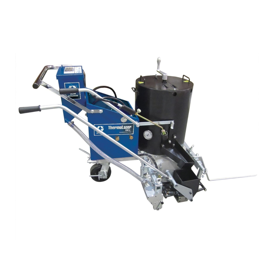
- For professional application of thermoplastic traffic marking compound materials
- For outdoor use only (not to be operated in rain or damp conditions) -
Fuel: LP Gas (Propane Vapor)
Burner capacities: See Technical Data, page 38.
Material capacity (max): 200-300 lb (91-136 kg)
IMPORTANT SAFETY INSTRUCTIONS
Read all warnings and instructions in this
manual. Save these instructions.
Related Manuals:
2
Repair
3A1320
Parts
3A1321
Double Bead Box 3A0004
3A1738
™
SmartDie
II
3A1738
™
FlexDie
®
200/200
/300
TC
™
Pavement Marking
(reflective beads applied simultaneously with screeding) -
ThermoLazer ProMelt
and
TC
ThermoLazer 200/200
ti22634b
ti23073a
3A1319K
TC
ThermoLazer 300
TC
ti23074a
EN
Advertisement
Table of Contents

Subscribe to Our Youtube Channel
Related Manuals for Graco ThermoLazer 200


Summary of Contents for Graco ThermoLazer 200
- Page 1 (reflective beads applied simultaneously with screeding) - - For outdoor use only (not to be operated in rain or damp conditions) - Fuel: LP Gas (Propane Vapor) ThermoLazer 200/200 Burner capacities: See Technical Data, page 38. Material capacity (max): 200-300 lb (91-136 kg)
-
Page 2: System Chart
‡ Requires 16” (40 cm) Conversion Bead System Kit for 300TC/ProMelt Only. - 17B190 Kit, accy, 16” (40 cm) Single Drop Bead System - 17B189 Kit, accy, 16” (40 cm) Double Drop Bead Box (requires 17B190 to be installed) FlexDie used on ThermoLazer 200/200 only FlexDie FlexDie Description Part No. -
Page 3: Table Of Contents
300TC/ProMelt) ..... 22 Graco Standard Warranty ....40... -
Page 4: Warnings
• Do not alter or modify equipment. • Use equipment only for its intended purpose. Call your Graco distributor for information. • Do not fill material beyond maximum capacity. • Route gas lines, hoses, wires and cables away from traffic areas, sharp edges, moving parts, and hot surfaces. - Page 5 Warnings WARNING PERSONAL PROTECTIVE EQUIPMENT Wear appropriate protective equipment when in the work area to help prevent serious injury, including eye injury, hearing loss, inhalation of toxic fumes, and burns. This protective equipment includes but is not limited to: • Clothing and respirator as recommended by the fluid, material, and solvent manufacturer.
-
Page 6: Component Identification - Thermolazer 200
ZZ Kettle Lid Lock M Screed Box/Bead Dispenser Box Actuator *LP-Gas supply cylinder not supplied by Graco. LP-Gas supply cylinder must be designed, fabricated, and marked in accordance with specifications and regulators for LP-Gas cylinders at The U.S. Department of Transportation (DOT),... - Page 7 Component Identification - ThermoLazer 200 Component Identification - ThermoLazer 200 (continued) ti22642b CC System Regulator AA Kettle Temperature Control Knob BB Kettle Temperature Indicator 3A1319K...
-
Page 8: Component Identification - Thermolazer 200Tc
M Rear Screed Box Manual Shut-Off N Torch *LP-Gas supply cylinder not supplied by Graco. LP-Gas supply cylinder must be designed, fabricated, and marked in accordance with specifications and regulators for LP-Gas cylinders at The U.S. Department of Transportation (DOT),... - Page 9 Component Identification - ThermoLazer 200TC Component Identification - ThermoLazer 200 (Continued) ti22641b AA Kettle Temperature Control Knob BB Kettle Temperature Indicator CC Kettle Gas Safety Valve DD System Regulator 3A1319K...
-
Page 10: Component Identification - Thermolazer 300Tc
SplitBead Hopper *LP-Gas supply cylinder not supplied by Graco. LP-Gas supply cylinder must be designed, fabricated, and marked in accordance with specifications and regulators for LP-Gas cylinders at The U.S. Department of Transportation (DOT), The National Standard of Canada, CAN/CSA-B339, Cylinders, Spheres, and Tubes for Transportation of Dangerous... - Page 11 Component Identification - ThermoLazer 300TC Component Identification - ThermoLazer 300 (Continued) ti25696a Kettle Temperature Control Knob Kettle Temperature Indicator Kettle Gas Safety Valve Kettle Pilot Burner Igniter Screed Box (SmartDie II) Front Screed Box Burners Flame Indicator Kettle Burners Manual Shut-Off Valve Kettle Burner Regulator Lifting Ring Lid/Lever Latch...
-
Page 12: Component Identification - Thermolazer Promelt
AB Torch SplitBead Hopper *LP-Gas supply cylinder not supplied by Graco. LP-Gas supply cylinder must be designed, fabricated, and marked in accordance with specifications and regulators for LP-Gas cylinders at The U.S. Department of Transportation (DOT), The National Standard of Canada, CAN/CSA-B339, Cylinders, Spheres, and Tubes for Transportation of Dangerous... - Page 13 Component Identification - ThermoLazer ProMelt Component Identification - ThermoLazer ProMelt (Continued) ti25697a Kettle Temperature Control Knob Kettle Temperature Indicator Kettle Gas Safety Valve Kettle Pilot Burner Igniter Screed Box (SmartDie II) Front Screed Box Burners Flame Indicator Kettle Burners Manual Shut-Off Valve Kettle Burner Regulator Lifting Ring Lid/Lever Latch...
-
Page 14: Important Safety Information
If a different sized fitting is needed, see your local LP gas equipment supplier. Front Screed Kettle Burner Box Burners (All ThermoLazer units) ti16989b ti14411a (All ThermoLazer units) Rear Screed Box Burners (ThermoLazer 300 /ProMelt) ti22561a Burner Burner Burner Burner ti22561b FlexDie Burners (ThermoLazer 200/200 3A1319K... -
Page 15: Important Safety Information
Important Safety Information Important Safety Information Front Screed Box Burners and Rear Screed Box Burn- ers will need to be ignited to test gas lines and fitting downstream of flame adjusting valve. NOTE: Kettle burners will need to be ignited to test gas If you do not follow these instructions exactly, a fire lines and fittings downstream of gas safety valves (CC). -
Page 16: Important Safety Information
Melting thermoplastic produces toxic fumes. Avoid prolonged inhalation of fumes. Air Openings DAILY: Check all gas lines and fittings for gas leaks. DAILY: Check gas supply hose for wear, abrasions, cuts or leaks. Replace only with hoses recommended by Graco. ti25699a 3A1319K... -
Page 17: Lighting Instructions
Lighting Kettle Burners ti23097a NOTE: Read Important Safety Information, page 14-16. ThermoLazer 200 FIRE AND EXPLOSION HAZARD 1. Open kettle door to view burner. If pilot ignites without depressing the gas safety valve knob, replace gas safety valve. If gas safety valve knob does not pop back after releasing in pilot posi- tion, STOP and replace gas safety valve. - Page 18 Lighting Instructions 2. Open propane tank valve. 8. Turn temperature control to desired setting. ThermoLazer 300 /ProMelt 1. Turn temperature control knob (AA) to “OFF”. ti14127a ti14124a 3. Turn gas safety valve (CC) to “PILOT” and push in. 2. Turn kettle gas safety valve (CC) to “OFF”. ti23102a ti14131b 4.
-
Page 19: Shutting Off Burner
“OFF” and observe that fails to light the pilot. main burners shut off. ThermoLazer 200 1. Turn gas safety valve to “OFF”. FIRE AND EXPLOSION HAZARD If main burners do not ignite or shut off when rotating temperature control knob, STOP. -
Page 20: Torch Lighting Instructions
Lighting Instructions ThermoLazer 300 /ProMelt 1. Turn gas safety valve to “OFF”. 2. Close kettle manual shut-off valve (KK) when finished heating with kettle burners. Close manual shut-off valve on propane tank when finished ti14127a melting and heating thermoplastic material. 2. -
Page 21: Front Screed Box Burner Lighting Instructions
ThermoLazer 300 /ProMelt ti14605a 2. Close manual shut-off valve on propane tank when finished melting and heating thermoplastic material. ThermoLazer 200/200 ti14128a ti23072a 6. Place torch at end of screed box burners to ignite Front Screed Box Burner and use screed box burners flame adjusting valve to Lighting Instructions adjust to desired flame. -
Page 22: Rear Screed Box Burner Lighting Instructions (Thermolazer 300Tc/Promelt)
Lighting Instructions Rear Screed Box Burner 5. Place torch at end of screed box burners to ignite and use screed box burners flame adjusting valve to Lighting Instructions adjust to desired flame. (ThermoLazer 300 /ProMelt) ThermoLazer shown Read Important Safety Information, page 14-16. 1. -
Page 23: Screed Box Thermolazer 200/200Tc (Flexdie)
Screed Box ThermoLazer 200/200TC (FlexDie) Screed Box ThermoLazer 200/200 (FlexDie) Installation 3. Replace and tighten bolt (a). Use extreme caution when installing and removing screed box. Expect all equipment components and material to be extremely hot. See MSDS for Thermo- plastic Traffic Marking Compound. -
Page 24: Removal
Screed Box ThermoLazer 200/200TC (FlexDie) Removal 4. Remove bolt and slide FlexDie box off. 1. Shut off screed box burners. Rear Front ti122669a 2. Remove the two gas hoses from quick release cou- plings (10). ti22677b BURN HAZARD Make sure to use two hands when picking up screed box. -
Page 25: Adjustments
Screed Box ThermoLazer 200/200TC (FlexDie) Adjustments 2. Slide mount left or right until edge of the frame is aligned with desired markings on bracket. For optimum delivery of the thermoplastic material, make sure the screed box is aligned to center on kettle trough. -
Page 26: Screed Box Thermolazer 300Tc/Promelt
Screed Box ThermoLazer 300TC/ProMelt (SmartDie II) Screed Box ThermoLazer 300 /ProMelt (SmartDie II) Installation ti17300a Use extreme caution when installing and removing screed box. Expect all equipment components and 5. Close and lock screed shroud door. material to be extremely hot. See MSDS for Thermo- plastic Traffic Marking Compound. -
Page 27: Adjustment
Screed Box ThermoLazer 300TC/ProMelt (SmartDie II) 2. Slide mount down until leading box edge of screed box runner is just off of the ground surface. For best performance, raise leading edge .020 in. (0.5 mm) off ground surface. Scraper blade may be used to BURN HAZARD set this depth. -
Page 28: Screed Box Line Thickness Adjustment
Screed Box Line Thickness Adjustment Screed Box Line Thickness Adjustment (All ThermoLazer units) # Turns # Turns ti17046a NOTE: 1/4 turn will change line thickness by .013 in. 1. Move screed box actuator to middle position. Make (0.3 mm). Turn the line adjustment screw clockwise for a sure screed box is closed and resting on the thinner line, or counterclockwise for a thickaer line. -
Page 29: Preparing Thermolazer 200/200Tc/300Tc For Application
Preparing ThermoLazer 200/200TC/300TC for Application Preparing ThermoLazer 200/200 for Application BURN HAZARD Keep all access covers closed and latched when equip- ment is in use. Always secure ThermoLazer by chocking wheels when adding thermoplastic. ti14122b 1. Secure the unit by chocking wheels and applying parking brake. -
Page 30: Preparing Thermolazer Promelt For Application
Preparing ThermoLazer ProMelt for Application Preparing ThermoLazer ProMelt for Application BURN HAZARD Keep all access covers closed and latched when equipment is in use. Always secure the unit by chocking wheels when adding thermoplastic. ti15951a 1. Secure the unit by chocking wheels and applying parking brake. -
Page 31: Promelt Overheating Protection
Adding Beads to SplitBead Hopper ti14410a Single Bead Application 15. Avoid bumping or impacting the unit to prevent spill- (ThermoLazer 200/200 age or splashing of hot material. 1. Open SplitBead hopper door. ProMelt Overheating Protection 2. Fill hopper with beads. -
Page 32: Applying Material To A Surface
Applying Material to a Surface Applying Material to a Double Bead Application (ThermoLazer 300TC/ProMelt) Surface (Requires Installation of Double Bead Kit 24C528) 1. Fill element beads on left side (smaller chamber). 2. Fill glass beads on right side (larger chamber). Close and lock hopper door. -
Page 33: Shutting Down
Shutting Down Shutting Down 1. Turn kettle gas safety valve (CC) to “OFF” position. ti14125a 5. Fully close torch flame adjusting valve. ti14626a 2. Turn temperature control knob (AA) to “OFF”. ti14605a 6. Turn main gas valve on propane tank OFF. ti14124a 3. -
Page 34: Clean-Up For Thermolazer 200/200Tc/300Tc
Clean-Up for ThermoLazer 200/200TC/300TC Clean-Up for ThermoLazer 200/200 /300 NOTICE Be sure to thoroughly clean all material out of screed box and any open areas to prevent material from freez- ing moving parts of screed box. Always run all material BURN HAZARD out of each screed box before removing. -
Page 35: Clean-Up For Thermolazer Promelt
Clean-Up for ThermoLazer ProMelt Clean-Up for ThermoLazer ProMelt 8. Repeat step 7. 9. Rotate agitator handle to 3 o’clock and hold at this position by using the cover latch. BURN HAZARD 10. Use small scraper to clean out trough, screed box, Never scoop out remaining melted thermoplastic from and agitators. -
Page 36: Maintenance
Maintenance Maintenance DAILY: Make sure LP-gas only flows to burner when safety shut-off valve knob is pressed in. DAILY: Make sure the screed burners are burning cor- rectly. DAILY: Check gas lines and fittings for gas leaks. Use soap and water mixture or LP-gas leak detector to DAILY: Check bead box dispenser drive wheel (27) and detect gas leaks. -
Page 37: Fattrack Front Swivel Wheel System
Maintenance FatTrack Front Swivel Wheel FatTrack Front Swivel Tire Alignment System Align front wheel as follows: (ThermoLazer 300 /ProMelt) 1. Loosen cap screw (86h). ANNUALLY: Tighten nut on screw under dust cap until spring washer bottoms out. Then back off the nut 1/2 to 3/4 turns. -
Page 38: Technical Data
Technical Data Technical Data ThermoLazer ThermoLazer 200/200 ThermoLazer 300 ProMelt (24U280) with Rear without Rear (24H624) Heat Heat (24U281) (24H622) (24H625) Fuel Liquefied Petroleum Gas (LP-gas) (propane vapor) Gas supply maximum pressure - psi (bar) 250 (17.24) Kettle burners (0.21) (0.034) (0.034) (0.21) -
Page 39: Notes
Notes Notes 3A1319K... -
Page 40: Graco Standard Warranty
With the exception of any special, extended, or limited warranty published by Graco, Graco will, for a period of twelve months from the date of sale, repair or replace any part of the equipment determined by Graco to be defective.
Need help?
Do you have a question about the ThermoLazer 200 and is the answer not in the manual?
Questions and answers