Table of Contents
Advertisement
Quick Links
Operation, Repair, Parts
LineDriver
For the propulsion of line striping and removal equipment. For professional use only. Not
approved for use in explosive atmospheres or hazardous (classified) locations.
Models: 25U670, 25U671
10 mph (16 kph) Maximum Operating Speed
Important Safety Instructions
Read all warnings and instructions in this manual and in related
LineLazer
®
equipment. Save these instructions.
Related Manuals:
Power Sonic Quick Guide (Scan QR code below)
710-0138
3A6720
LineDriver ES Lithium
Model
Series
---
25U670
25U671
Use only genuine Graco replacement parts.
The use of non-Graco replacement parts may void warranty.
ES Lithium
®
, GrindLazer
and ThermoLazer
®
Delta-Q Battery Charger
Hitch Receiver Kit
Cord Adapter
B
North America
North America
Australia
CEE 7/7
B
Denmark
Italy
Switzerland
United Kingdom
manuals before using the
®
3A9034B
EN
Advertisement
Table of Contents
Troubleshooting

Related Manuals for Graco LineDriver ES 25U670


Summary of Contents for Graco LineDriver ES 25U670
- Page 1 3A6720 Hitch Receiver Kit LineDriver ES Lithium Model Series Cord Adapter 25U670 North America North America Australia CEE 7/7 25U671 Denmark Italy Switzerland United Kingdom Use only genuine Graco replacement parts. The use of non-Graco replacement parts may void warranty.
-
Page 2: Table Of Contents
Graco Standard Warranty....39 Graco Information......39... -
Page 3: Warnings
Warnings Warnings The following warnings are for the setup, use, grounding, maintenance, and repair of this equipment. The exclamation point symbol alerts you to a general warning and the hazard symbols refer to procedure-specific risks. When these symbols appear in the body of this manual or on warning labels, refer back to these Warnings. Product-specific hazard symbols and warnings not covered in this section may appear throughout the body of this manual where applicable. - Page 4 Do not leave battery unattended while charging. • Immediately unplug charger when charging is complete. • Charge only Graco approved batteries listed in this manual; other batteries may burst. • Use only in dry locations. Do not expose to water or rain. •...
- Page 5 Warnings GROUNDING This product must be grounded. In the event of an electrical short circuit, grounding reduces the risk of electric shock by providing an escape wire for the electric current. This product is equipped with a cord having a grounding wire with an appropriate grounding plug. The plug must be plugged into an outlet that is properly installed and grounded in accordance with all local codes and ordinances.
-
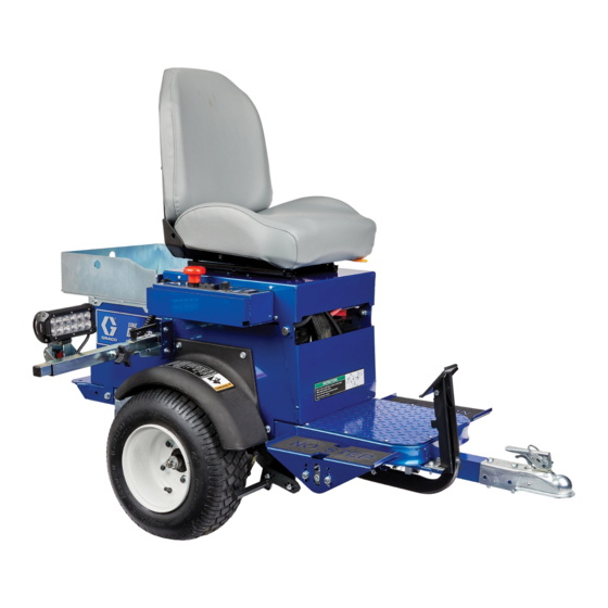
Page 6: Component Identification
Component Identification Component Identification Power Switch Headlight Speed Switch Direction/Speed Pedals ™ Step Plate ExactMil Speed Control Hitch Voltage Meter Coupler 12V Aux. Power Safety Pin Location Light Socket Handle Open Motor Controller Diagnostic Light Handle Locked Battery Charger Parking/Emergency Brake Seat Lid Tool Tray Buzzer... -
Page 7: Setup
Setup Setup 1. Install supplied ramp onto pallet. 5. Insert safety pin in latch 2. Connect Hitch Receiver to line striping or line removal equipment - Hitch Receiver Kit 25N787; Manual 3A6720. ti11086a 6. Adjust seat forward/backward with lever below seat. ti11085a 7. -
Page 8: Startup
Startup Startup Know Your Controls Speed Switch ™ ExactMil (Speed Control) Mode Direction/Speed Pedals ExactMil Mode ensures a consistent paint thickness by The Direction/Speed Pedals drive the LineDriver holding the speed steady. To enable ExactMil mode: forward and in reverse. Switching from forward to reverse creates a braking action. -
Page 9: Daily Inspections
Startup Daily Inspections Incline/ECO Mode Incline/ECO Mode is the recommended default mode Perform the following inspections each day before for all operations. It is helpful when greater control is using the LineDriver ES Lithium. needed such as during loading or unloading and in congested areas. -
Page 10: Operation
Operation Operation Differences in Operation 5. Push striper or grinder handle bars to begin desired turn. The LineDriver ES Lithium operates differently than a gasoline powered LineDriver. 1. LineDriver ES rolls freely, especially on inclines, when the power is off. Set Parking/Emergency Brake before turning off. -
Page 11: Operating On Inclines
Operation Starting and Stopping on an Incline 7. Engage Parking/Emergency Brake when not operating LineDriver. This prevents rolling when on 1. Engage the Parking/Emergency Brake before an incline. turning the Power Switch to OFF when parking on an incline. 2. Turn the Power Switch to ON, and allow the machine to initialize before releasing the Parking/Emergency Brake when starting on an incline. -
Page 12: Charging The Batteries
Operation Charging the Batteries 5. Plug charging cord into charging port on the unit. Connect an extension cord, per charger manual, to the charging cord and plug it into wall power. 6. Always unplug the battery charger when the batteries reach full charge. Replace and charge battery only in well-ventilated area and away from flammable or combustible materials, including paints and solvents. - Page 13 Operation 7. The Charging Output Indicator means that the NOTE: The Charge Display may show codes to indicate charger output is active. different conditions. Refer to charger manual for additional information. 8. When power is connected, charger will immediately begin charging. •...
-
Page 14: Maintenance
Maintenance Maintenance Parking/Emergency Brake 5. Install two bolts and secure brake rod. Repeat for second tire. Adjustment or Replacement 1. Block tires so LineDriver will not move. Release Parking/Emergency Brake. 2. Ensure Power Switch is in OFF position. 3. Inflate tires to operating pressure per tire sidewall. Remove two bolts securing brake rod. -
Page 15: Throttle Linkage Adjustment
Maintenance Throttle Linkage Adjustment 3A9034B... -
Page 16: Coupler Adjustment
Maintenance Coupler Adjustment A Coupler too tight or too loose needs to be adjusted. Ensure Power Switch is in OFF position. Before adjusting, check ball and Coupler for wear. Replace entire Coupler if unable to tighten it. 3A9034B... -
Page 17: Accelerator Calibration (Using Kit 25N880)
Maintenance Accelerator Calibration (Using Kit 25N880) 1. Turn power OFF. Engage Parking/Emergency 8. Rotate accelerator arm back and forth, then return Brake. it to neutral position. Re-adjust voltage if necessary. Turn power OFF. 2. Slowly raise hitch Coupler until LineDriver rests on rear bumper. -
Page 18: Transaxle Service
Maintenance Transaxle Service Check Oil Level (Annually) Change Oil (recommended every 3 years) 1. Turn power OFF. Engage Parking/Emergency 1. Turn power OFF. Engage Parking/Emergency Brake. Brake. 2. Slowly raise hitch Coupler until LineDriver rests on 2. Slowly raise hitch Coupler until LineDriver rests on rear bumper. -
Page 19: Repair
Repair Repair Battery Pack Replacement 5. Remove battery cables. Always disconnect negative (black) cables prior to disconnecting positive (red) cables. NOTE: Prior to replacing batteries, refer toTroubleshooting - LineDriver, page 22, to determine if the batteries are the cause of the problem. Never mix battery types or brands. -
Page 20: Transaxle Replacement
Repair Transaxle Replacement Motor Controller Replacement 1. Turn power OFF. 1. Turn power OFF. 2. Remove rear screws of Seat Lid. Pivot seat forward 2. Remove rear screws of Seat Lid. Pivot seat forward slowly. slowly. 3. Disconnect battery cables to motor controller. 3. -
Page 21: Recycling And Disposal
Recycling and Disposal Recycling and Disposal Rechargeable Battery Disposal End of Product Life Do not place batteries in the trash. Recycle batteries At the end of the product’s useful life, dismantle and according to local regulations. In the USA and Canada, recycle it in a responsible manner. -
Page 22: Troubleshooting - Linedriver
Troubleshooting - LineDriver Troubleshooting - LineDriver PROBLEM CAUSE SOLUTION Parking/Emergency Brake Parking Brake needs adjustment Adjust Parking Brake does not keep LineDriver from moving Tire pressure too low Adjust pressure per tire sidewall LineDriver creeps in forward or reverse Throttle linkage too long or too short Adjust throttle linkage direction Head light does not turn on... -
Page 23: Troubleshooting - Motor Controller
Troubleshooting - Motor Controller Troubleshooting - Motor Controller Diagnostics Summary of LED Display Formats Diagnostics information can be obtained by observing The two LEDs have four different display modes, the fault codes issued by the Status LEDs. See Table 1 indicating the type of information they are providing. - Page 24 Troubleshooting - Motor Controller NOTE: When a fault is encountered, shut off the Power Switch and turn it back on to see if the fault clears. If it does not, shut off the Power Switch and remove the 35-pin connector. Check the connector for corrosion or damage, clean if necessary, and re-insert connector.
- Page 25 Troubleshooting - Motor Controller CODE DESCRIPTION POSSIBLE CAUSE SET / CLEAR CONDITIONS SOLUTION Non-controller system Inspect all cables and drain on battery. connectors from batteries to Battery resistance too controller. Set: Battery pack voltage high. Let battery cool then fully dropped below the Severe Battery disconnected recharge battery.
- Page 26 Troubleshooting - Motor Controller CODE DESCRIPTION POSSIBLE CAUSE SET / CLEAR CONDITIONS SOLUTION Normal operation. Fault shows that regen braking currents elevated the battery Continue using the unit. Set: Battery pack voltage voltage during regen Inspect all cables and exceeded the Overvoltage limit. B+ Overvoltage braking.
- Page 27 Troubleshooting - Motor Controller CODE DESCRIPTION POSSIBLE CAUSE SET / CLEAR CONDITIONS SOLUTION Main contactor did not close. Inspect contactor cable and Main contactor tips are connectors. oxidized, burned, or not Set: With the main contactor Inspect all cables and making good contact.
-
Page 28: Parts Drawing
Parts Drawing Parts Drawing Torque cable cap screws or nuts to 7-8 ft-lbs (9-11 N·m) 3A9034B... -
Page 29: Parts Drawing
Parts Drawing Parts Drawing Torque to 8-9 ft-lbs (11-12 N·m) Torque to 40-60 ft-lbs (54-81 N·m) in criss-cross sequence Torque to 16-20 ft-lbs (22-27 N·m) Torque to 10-11 ft-lbs (14-15 N·m) 3A9034B... -
Page 30: Parts Drawing - Detail Views
Parts Drawing - Detail Views Parts Drawing - Detail Views Torque to 6-7 ft-lbs. (8-9 N·m) Torque to 20-25 ft-lbs (27-34 N·m) Torque to 90-115 ft-lbs (122-156 N·m) Torque to 95-105 in-lbs (10.7-11.9 N·m) Use a wrench to support backup nuts firmly while tightening. -
Page 31: Parts Drawing
Parts Drawing Parts Drawing Clamped parts must move freely after tightening 3A9034B... -
Page 32: Parts List
Parts List Parts List Ref. Part Description Ref. Part Description 25N471 CARRIAGE 25N649 FRAME, electric LineDriver 25N476 LID, seat, paint 15N470 PLATE, floor 100424 SCREW, cap, hex hd 25N776 KIT, throttle, includes 180 801020 NUT, lock, hex 15R872 INSERT, bearing, flange 113796 SCREW, flanged, hex hd 116887 BEARING, flanged, bronze 25N477 BASE, controls, paint... - Page 33 Parts List Ref. Part Description Ref. Part Description 17R099 TUBE, bracket, light, LED 110963 SCREW, cap, flange hd 17R098 LIGHT, LED 126215 TRIM, edge, protection 111145 KNOB, pronged 17Z070 KIT, carrier, cover 114425 BUSHING, strain relief 17Z071 KIT, axle, hub 15R308 CORD, power 17Z072 AXLE, vent, cap 15R864 KNOB...
-
Page 34: Wiring Diagram - Harness 25N661
Wiring Diagram - Harness 25N661 Wiring Diagram - Harness 25N661 3A9034B... -
Page 35: Wiring Diagram
Wiring Diagram Wiring Diagram 3A9034B... -
Page 36: Wiring Diagram - Harness 25E406
Wiring Diagram - Harness 25E406 Wiring Diagram - Harness 25E406 3A9034B... -
Page 37: Technical Specifications
Technical Specifications Technical Specifications LineDriver ES Lithium U.S. Metric Dimensions Height 48.5 in. 1232 mm Width 29.3 in. 744 mm Length 58.2 in. 1478 mm Weight 620 lbs. 281 kg Speed Forward 0-10 mph 0-16 kph Reverse 0-6 mph 0-10 kph Batteries Nominal Battery Pack Voltage 24 VDC... - Page 38 If in a condition that it can no longer operate, it should be taken out of service and dismantled. Individual parts should be sorted by material and disposed of properly. Key construction materials can be found in the Materials of Construction Section. Graco Date Code/Serial Month (First Year (2nd and 3rd...
-
Page 39: Graco Standard Warranty
With the exception of any special, extended, or limited warranty published by Graco, Graco will, for a period of twelve months from the date of sale, repair or replace any part of the equipment determined by Graco to be defective. - Page 40 Original instructions. This manual contains English. MM 3A9034 Graco Headquarters: Minneapolis International Offices: Belgium, China, Japan, Korea GRACO INC. AND SUBSIDIARIES • P.O. BOX 1441 • MINNEAPOLIS MN 55440-1441 • USA Copyright 2021, Graco Inc. All Graco manufacturing locations are registered to ISO 9001. www.graco.com...
Need help?
Do you have a question about the LineDriver ES 25U670 and is the answer not in the manual?
Questions and answers