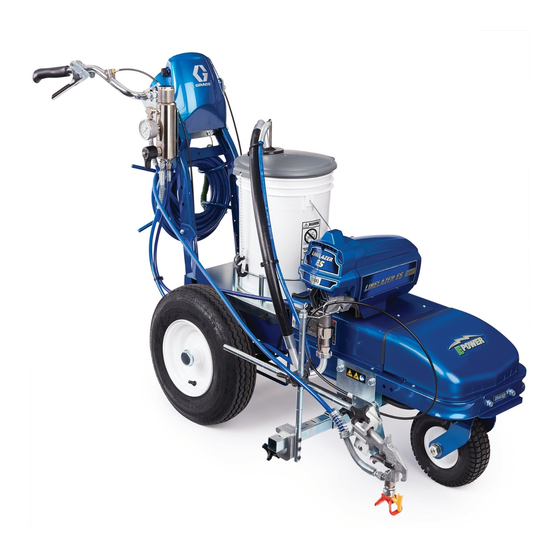
Graco LineLazer ES 1000 Installation, Repair, Parts
Airless line striper
Hide thumbs
Also See for LineLazer ES 1000:
- Operation - repair - parts (60 pages) ,
- Instructions manual (14 pages) ,
- Operation - repair - parts (38 pages)
Table of Contents
Advertisement
Operation, Repair, Parts
™
LineLazer
Airless Line Striper
For the application of line striping materials.
For professional use only.
Not approved for use in explosive atmospheres or hazardous locations.
Maximum Operating Pressure: 3300 psi (22.8 MPa, 228 bar)
Important Safety Instructions
Read all warnings and instructions in this manual and in related manuals
before using the equipment. Be familiar with the controls and the proper
usage of the equipment. Save these instructions.
Related Manuals:
ES 1000
ES 2000
311254
Gun
311254
334599
Pump
310643
3A3428
Use only genuine Graco replacement parts.
The use of non-Graco replacement parts may void warranty.
ES 1000 / ES 2000
Gun
Pump
Auto-Layout Application Methods
LineLazer ES 1000
LineLazer ES 2000
3A4603F
EN
Advertisement
Table of Contents
Troubleshooting

Related Manuals for Graco LineLazer ES 1000


Summary of Contents for Graco LineLazer ES 1000
- Page 1 Save these instructions. Related Manuals: ES 1000 ES 2000 311254 311254 334599 Pump 310643 Pump 3A3428 Auto-Layout Application Methods LineLazer ES 2000 LineLazer ES 1000 Use only genuine Graco replacement parts. The use of non-Graco replacement parts may void warranty.
-
Page 2: Table Of Contents
Contents Contents Models ........4 LineLazer V LiveLook Display ....30 Warnings . - Page 3 Parts Drawing - ES 2000 ....98 Graco Information ......119 Parts List - ES 2000 .
-
Page 4: Models
Models Models LineLazer ES 1000 Model 1 Battery 2 Batteries Included Included 25M226 120V 25N784 120V 25M228 230V 25N785 230V LineLazer ES 2000 Model 2 Batteries Standard HP Auto Number of Number of 120V 230V LazerGuide... -
Page 5: Warnings
Warnings Warnings The following warnings are for the setup, use, grounding, maintenance, and repair of this equipment. The exclamation point symbol alerts you to a general warning and the hazard symbols refer to procedure-specific risks. When these symbols appear in the body of this manual or on warning labels, refer back to these Warnings. Product-specific hazard symbols and warnings not covered in this section may appear throughout the body of this manual where applicable. - Page 6 Check hoses and parts for signs of damage. Replace any damaged hoses or parts. • This system is capable of producing 3300 psi (22.8 MPa, 228 bar). Use Graco replacement parts or accessories that are rated a minimum of 3300 psi (22.8 MPa, 228 bar).
- Page 7 Warnings EQUIPMENT MISUSE HAZARD Misuse can cause death or serious injury. • Do not operate the unit when fatigued or under the influence of drugs or alcohol. • Do not exceed the maximum working pressure or temperature rating of the lowest rated system component.
- Page 8 Warnings PERSONAL PROTECTIVE EQUIPMENT Wear appropriate protective equipment when in the work area to help prevent serious injury, including eye injury, hearing loss, inhalation of toxic fumes, and burns. This protective equipment includes but is not limited • Protective eyewear, and hearing protection. •...
-
Page 9: Component Identification (Es 1000)
Component Identification (ES 1000) Component Identification (ES 1000) PRIME SPRAY ti30321a 10 Inverter Circuit Breakers ON/OFF Switch 11 Pump Pressure Control & Display 12 Trigger Safety Spray Gun Trigger 13 Fuse Turn Control 14 Charging Port Filter 15 Voltage Meter Pressure Gauge 16 LED Status Center &... -
Page 10: Component Identification (Es 2000)
Component Identification (ES 2000) Component Identification (ES 2000) 10 Inverter Circuit Breakers ON/OFF Switch 11 Pump Pressure Control & Display 12 Trigger Safety Spray Gun Trigger 13 Fuse Turn Control 14 Charging Port Filter 15 Voltage Meter Laser 16 LED Status Center & Battery Type Selector Prime/Pressure Valves Access Drain and Siphon Hoses... -
Page 11: Tip Selection
Tip Selection Tip Selection (cm) (cm) (cm) (cm) LL5213* 2 (5) LL5215* 2 (5) LL5217 4 (10) LL5219 4 (10) LL5315 4 (10) LL5317 4 (10) LL5319 4 (10) LL5321 4 (10) LL5323 ... -
Page 12: Battery And Charger
100% depth each cycle. Battery Type and Charging Profiles Graco recommends using a 12V 100 Ahr Absorbent Only use batteries that allow an initial charge rate of 30 Glass Mat (AGM) DEEP CYCLE battery.The charger is amps or higher. -
Page 13: Charging The Battery
Battery and Charger Charging the Battery 3. Plug charging cord into charging port on the unit. Connect an extension cord, minimum 12AWG (2.5mm ), to the charging cord and plug it into wall power. Replace and charge battery only in well-ventilated area and away from flammable or combustible materials, including paints and solvents. -
Page 14: Grounding Procedure
Grounding Procedure (AC Wall Power) Grounding Procedure Do not place pail on a non-conductive surface such as paper or cardboard which interrupts grounding (AC Wall Power) continuity. This equipment must be grounded to reduce the risk of static sparking and electric shock. An electric shock or static spark can cause fumes to ignite or explode. -
Page 15: Grounding Procedure
Grounding Procedure (Battery Power) (For Flammable Flushing Fluids Only) Grounding Procedure Do not place pail on a non-conductive surface such as paper or cardboard which interrupts grounding (Battery Power) (For Flammable continuity. Flushing Fluids Only) This equipment must be grounded to reduce the risk of static sparking. -
Page 16: Pressure Relief Procedure
Pressure Relief Procedure Pressure Relief Procedure 3. Turn pressure control to lowest setting. Trigger all guns to relieve pressure. This equipment stays pressurized until pressure is manually relieved. To help prevent serious injury from ti30323a pressurized fluid, such as skin injection, splashing fluid 4. -
Page 17: Setup/Startup
Setup/Startup Setup/Startup 6. If removed, install strainer. 1. Perform Pressure Relief Procedure, page 16. ti27612a 2. Charging the Battery, page 13. 7. Turn prime valve down. Turn pressure control counterclockwise to lowest pressure. 3. Perform Grounding Procedure (AC Wall Power), page 14, or Grounding Procedure (Battery Power) (For Flammable Flushing Fluids Only), page 15, if using flammable materials. - Page 18 Setup/Startup 10. ES 1000: Turn pressure control to prime. Allow fluid 13. Inspect fittings for leaks. If leaks occur, turn sprayer to circulate for 15 seconds. OFF immediately. Perform Pressure Relief Procedure, page 16. Tighten leaky fittings. Repeat ES 2000: Increase pressure 1/2 turn to start motor Setup/Startup, steps 1 - 13.
-
Page 19: Switchtip And Guard Assembly
Setup/Startup SwitchTip and Guard Assembly To avoid serious injury from skin injection do not put your hand in front of the spray tip when installing or removing the spray tip and tip guard. 1. Engage trigger lock. Use end of SwitchTip to press OneSeal into tip guard, with curve matching tip bore. -
Page 20: Gun Placement
Gun Placement Gun Placement Another option can be to swing the gun out at an angle and rotate the tip guard. This results in better visibility for the user. Install Gun 1. Insert guns into gun holder. Tighten clamps. ti27777a Position Gun ti28130a 2. -
Page 21: Select Auto Guns (Es 2000)
Gun Placement Select Auto Guns (ES 2000) 1. Use the gun selector buttons to determine which 2. Use the gun trigger control to actuate auto guns. guns are active. Each gun selector has 3 settings: continuous line, OFF and programmed line pattern. ti27881a ti27784a 4 Examples:... -
Page 22: Gun Positions Chart
Gun Placement Gun Positions Chart ti27786a One line One line up to 24 in. (61cm) wide Two lines One line or two lines to spray around obstacles One gun curb Two gun curb Two lines or one line up to 24 in. (61 cm) wide 3A4603F Operation, Repair, Parts... -
Page 23: Gun Arm Mounts
Gun Placement Gun Arm Mounts 3. Slide gun arm assembly into desired gun arm mounting slot. This unit is equipped with front and rear gun arm mounts. ti27797a 4. Tighten gun arm knob into gun arm mounting slot. ti27798a NOTICE Make sure all hoses, cables, and wires are properly ti30326a routed through brackets and do NOT rub on tire. -
Page 24: Installation
Gun Placement Installation No fluid spray 2. Turn screw in handle clockwise if spray icon 1. Install vertical gun mount onto gun bar. appears before fluid spray starts. ti27801a NOTE: Make sure all hoses, cables, and wires are properly routed through brackets. ti27802a No spray icon Trigger Sensor Adjustment (ES... -
Page 25: Gun Cable Adjustment
Gun Placement 3. Insert plastic cable retainer into cable bracket hole. Gun Cable Adjustment Adjusting the gun cable will increase or decrease the gap between the trigger plate and the gun trigger. To adjust trigger gap, perform the steps below. ES 1000 &... -
Page 26: Straight Line Adjustment
Gun Placement Straight Line Adjustment 4. Roll the striper. Repeat steps 2 and 3 until striper rolls straight. Tighten bolt on wheel alignment plate to lock the new wheel setting. The front wheel is set to center the unit and allow the operator to form straight lines. -
Page 27: Paint Stripe Width
Paint Stripe Width Paint Stripe Width 1. Adjust gun up or down to change paint stripe width. 2. Trigger gun and spray test pattern. Slowly adjust pressure to eliminate heavy edges. Use smaller tip size if pressure adjustment can not eliminate heavy edges. -
Page 28: Cleanup
Cleanup Cleanup Flush Drain Tube 6. Remove fluid intake and drain tube from paint, wipe excess paint off outside. 1. Perform Pressure Relief Procedure, page 16. 2. Remove guard and SwitchTip from all guns. TI3371A 7. Place siphon tube set in grounded metal pail partially filled with flushing fluid. -
Page 29: Flush Hose And Gun
Cleanup Flush Hose and Gun 10. To flush airless hose and spray gun, turn prime 12. Stop triggering gun. valve horizontal. 13. Fill pump with Pump Armor and reassemble filter, 11. Hold gun against waste pail. Disengage trigger lock. guard and SwitchTip. Trigger gun and turn pressure control to Fast Flush 14. -
Page 30: Linelazer V Livelook Display
LineLazer V LiveLook Display LineLazer V LiveLook Display ES 2000 (Standard Series) 3A4603F Operation, Repair, Parts... -
Page 31: Initial Setup (Es 2000 Standard Series)
LineLazer V LiveLook Display Initial Setup (ES 2000 Standard Series) The initial setup prepares the striper for operation based US Units on a number of user entered parameters. Language Pressure = psi selections and the units of measure selections can be Volume = gallons set before you start or changed later. - Page 32 LineLazer V LiveLook Display 3. Press to select Setup/Information. 6. Push to start calibration. ti27826a 7. Move striper forward. Keep unit aligned with steel tape. 8. Stop when chosen part of unit aligns with 26-ft (8m), or distance entered, on steel tape (25-ft./ 7.6m dis- ti27827a tance).
-
Page 33: Striping Mode (Es2000 Standard Series)
LineLazer V LiveLook Display Striping Mode (ES2000 Standard Series) Operating in Striping Mode Ref. Description 1. Make sure ON/OFF switch is ON position. Resets Distance, Gallons, Mils *2 Job logging 2. Set pump switch to ON. Scroll between menu screens Line width adjustment buttons *5 Auto gun buttons MIL thickness. -
Page 34: Measure Mode (Es2000 Standard Series)
LineLazer V LiveLook Display Measure Mode (ES2000 Standard Series) Measure Mode replaces a tape measure to measure 2. Press and release . Move striper forwards or distances when laying out an area to be striped. backwards. (Moving backwards is a negative dis- tance.) 1. -
Page 35: Setup/Information
LineLazer V LiveLook Display Setup/Information to select Setup/Information. Press to select Language. See Language, page 31. See Calibration, page 31. See Settings, page 36. See Information, page 37. ti27835b 3A4603F Operation, Repair, Parts... -
Page 36: Settings
LineLazer V LiveLook Display Settings to select Setup/Information. Press open Settings Menu. Chooses the machine type. Necessary for accurate gallon counting. to set time and date. Set units with to adjust screen contrast to the desired value. 3A4603F Operation, Repair, Parts... -
Page 37: Information
LineLazer V LiveLook Display Information to select Setup/Information. Press open Information Menu. Displays and logs life data and striper information. View and test functionality of components. Stroke Counter Touch Pad Buttons Pressure Transducer Distance Sensor Battery Voltage Logs last four error codes that occurred. Code Description 02 = Over pressure 03 = No transducer detected... -
Page 38: Es2000 (Hp Auto Series)
ES2000 (HP Auto Series) ES2000 (HP Auto Series) 3A4603F Operation, Repair, Parts... -
Page 39: Linelazer V Livelook Display
LineLazer V LiveLook Display LineLazer V LiveLook Display ES2000 (HP Auto Series) 3A4603F Operation, Repair, Parts... -
Page 40: Initial Setup (Es2000 Hp Auto Series)
LineLazer V LiveLook Display Initial Setup (ES2000 HP Auto Series) The initial setup prepares the striper for operation based US Units on a number of user entered parameters. Language Pressure = psi selections and the units of measure selections can be Volume = gallons set before you start or changed later. - Page 41 LineLazer V LiveLook Display 6. Press and release gun trigger control to start cali- 3. Press to select Setup/Information. bration. ti27912a 7. Move striper forward. Keep laser dot on steel tape. 8. Stop when laser aligns with 26-ft (8m) or distance entered on steel tape (25-ft./7.6m distance).
-
Page 42: Striping Mode (Es2000 Hp Auto Series)
LineLazer V LiveLook Display Striping Mode (ES2000 HP Auto Series) Operating in Striping Mode Ref. Description Striper must be running before activating gun trigger Select a “Favorite”, press for less than one sec- control. ond. 1. Make sure ON/OFF switch is ON position. Save a “Favorite”, press and hold for more than three seconds. -
Page 43: Measure Mode (Es2000 Hp Auto Series)
LineLazer V LiveLook Display Measure Mode (ES2000 HP Auto Series) Measure Mode replaces a tape measure to measure 2. Press and release gun trigger control. Move striper distances when laying out an area to be striped. forwards or backwards. (Moving backwards is a negative distance.) 1. -
Page 44: Layout Mode
LineLazer V LiveLook Display Layout Mode 2. Use gun activation buttons to select guns. Layout Mode is used to calculate and mark parking lot stalls. 1. Use to select Layout Mode. ti27918a 3. Press and release gun trigger control and move striper forward. -
Page 45: Stall Calculator
LineLazer V LiveLook Display Stall Calculator 2. The most recent length measured in Measure Mode is automatically displayed. Press gun trigger control to start a new measurement. Press again to stop Stall Calculator is used to set the stall size. The striper measuring. -
Page 46: Angle Calculator
LineLazer V LiveLook Display Angle Calculator 2. Dot spacing (B) and offset (C) are calculated based on the parameters entered: Angle Calculator is used to determine the offset value Stall angle and dot spacing value for a layout. Stall depth Stall size (width) 1. - Page 47 LineLazer V LiveLook Display 5. Press and release gun trigger control to start 4. Press to transfer calculated dot spacing marking stall size dots. Press and release gun distance to Layout Mode. Save this value in trigger control to stop marking. favorites if desired.
-
Page 48: Setup/Information
LineLazer V LiveLook Display Setup/Information to select Setup/Information. Press to select Language. See Language, page 31. See Calibration, page 31. See Settings, page 49. See Information, page 50. See Marker Layout Mode, page 51. 3A4603F Operation, Repair, Parts... -
Page 49: Settings
LineLazer V LiveLook Display Settings to select Setup/Information. Press open Settings Menu. Chooses the machine type. Necessary for accurate gallon counting. to set time and date. Needed for accurate Data Logging. Set units with to adjust screen contrast to the desired value. For programmed skip lines, press to choose: In Auto-mode, guns won’t fire or will shut off if speed is below set... -
Page 50: Information
LineLazer V LiveLook Display Information to select Setup/Information. Press open Information Menu. Displays and logs life data and striper information. View and test functionality of component Stroke Counter Touch Pad Buttons Pressure Transducer Distance Sensor Battery Voltage Logs last four error codes that occurred. Code Description 02 = Over pressure 03 = No transducer detected... -
Page 51: Marker Layout Mode
LineLazer V LiveLook Display Marker Layout Mode 4. Set gun switch to skip line or solid line. The Marker Layout Mode feature sprays a dot or a series of dots to mark an area. 1. Use to select Setup/Information. Press ti27918a to open Marker Layout Mode. -
Page 52: Data Logging
LineLazer V LiveLook Display Data Logging The LLV control is equipped with Data Logging, which 1. Press the to open the Data Logging pop up allows the user to recall job data and export the data window. from the machine to a USB drive. 2. -
Page 53: Maintenance
Maintenance Maintenance Routine maintenance is important to ensure proper operation of your sprayer. Maintenance includes performing routine actions which keep your sprayer in operation and prevents trouble in the future. Activity Interval Inspect/clean sprayer filter, fluid inlet strainer, and gun filter. Daily or each time you spray Inspect motor shield vents for blockage. -
Page 54: Troubleshooting (Es 1000 & Es 2000)
Troubleshooting (ES 1000 & ES 2000) Troubleshooting (ES 1000 & ES 2000) Mechanical/Fluid Flow , page 16, before Follow Pressure Relief Procedure checking or repairing. 2. Check all possible problems and causes before disassembling the unit. What to Do What to Check When check is not OK, refer to this Problem If check is OK, go to next check... - Page 55 Troubleshooting (ES 1000 & ES 2000) What to Do What to Check When check is not OK, refer to this Problem If check is OK, go to next check column Motor runs but pump does not stroke Connecting rod assembly damaged. Replace connecting rod assembly.
-
Page 56: Electrical (Es 1000)
(for example: two blinks equals CODE 02). Error Code Messages CODE MESSAGE ACTION HIGH PRESSURE DETECTED - Check for clogs. Use only Graco spray hoses, use a RELIEVE PRESSURE minimum of 50ft/15m. PRESSURE TRANSDUCER NOT Check transducer connection. DETECTED MOTOR NOT SPINNING Check for mechanical failure and check motor connections. - Page 57 Troubleshooting (ES 1000 & ES 2000) Problem What to Check How to check Sprayer does not run at all Make sure there is no pressure in the system (see Check transducer or Pressure Relief Procedure, page 16). Check fluid path transducer connections for clogs, such as clogged filter.
- Page 58 Troubleshooting (ES 1000 & ES 2000) Problem What to Check How to check Sprayer does not run at all Control is commanding motor to Remove pump and try to run sprayer. If motor runs, run but motor shaft does not check for locked or frozen pump or drive train.
- Page 59 Troubleshooting (ES 1000 & ES 2000) Problem What to Check How to check Perform Field Short Test: Test at large 4-pin motor field connector. There should not be continuity from pin 4, the ground wire, and any of the remaining 3 pins.
-
Page 60: Es 2000 Troubleshooting
Troubleshooting (ES 1000 & ES 2000) Problem What to Check How to check Low battery Check the condition of the batteries and recharge if AC output voltage is low and the inverter turns loads OFF in a short possible. time. AC voltage has dropped Check the AC voltage for proper voltage and frequency. - Page 61 Troubleshooting (ES 1000 & ES 2000) Problem What to Check How to check Spray icon is always shown on dis- Interrupter is improperly posi- Turn screw clockwise until spray icon is synchronized play. tioned. with fluid spray, page 24. Reed switch assembly is dam- Replace reed switch assembly.
-
Page 62: Electrical (Es 2000)
Troubleshooting (ES 1000 & ES 2000) Electrical (ES 2000) Symptom: Sprayer does not run, stops running, or will 4. Remove control box cover to view control board not shut off. status light. To determine which code refer to the control board status light. Turn the ON/OFF switch OFF, remove the control cover then turn power back ON. - Page 63 Troubleshooting (ES 1000 & ES 2000) TYPE OF PROBLEM WHAT TO CHECK HOW TO CHECK Sprayer does not run at all Check transducer or transducer Set sprayer to OFF and disconnect power to connections (control board is not sprayer. Control board status light blinks detecting a pressure signal).
- Page 64 Troubleshooting (ES 1000 & ES 2000) TYPE OF PROBLEM WHAT TO CHECK HOW TO CHECK Sprayer does not run at all Control is commanding motor to run Remove pump and try to run sprayer. If motor runs, but motor shaft does not rotate. check for locked or frozen pump or drive train.
- Page 65 Troubleshooting (ES 1000 & ES 2000) TYPE OF PROBLEM WHAT TO CHECK HOW TO CHECK Sprayer does not run at all Control is commanding motor to run Perform Field Short Test: Test at large 4-pin motor but motor shaft does not rotate. field connector.
- Page 66 Troubleshooting (ES 1000 & ES 2000) TYPE OF PROBLEM WHAT TO CHECK HOW TO CHECK Sprayer does not run at all Allow sprayer to cool. If sprayer NOTE: Motor must be cooled down for the test. runs when cool, correct cause of Control board status light blinks Check thermal device connector (yellow wires) overheating.
- Page 67 Troubleshooting (ES 1000 & ES 2000) TYPE OF PROBLEM WHAT TO CHECK HOW TO CHECK Sprayer does not run at all Check the connections. Control Turn power OFF. is not receiving a motor position Control board status light blinks Disconnect motor position sensor and inspect for sensor signal 16 times repeatedly damage at connectors.
-
Page 68: Sprayer Will Not Run (Es 1000 & Es 2000)
Troubleshooting (ES 1000 & ES 2000) Sprayer Will Not Run (ES 1000 & ES 2000) (See following page for steps) Remove Control box cover. Turn sprayer ON. Observe control board status light on See Step 1. Do you control board (see page 62). have over 100 VAC (220 VAC for 230v units)? No Light... - Page 69 Troubleshooting (ES 1000 & ES 2000) Step 1: Step 3: Step 2: Plug Power cord in and turn Check motor thermal switch. Disconnect potentiometer. switch ON. Connect probes Unplug yellow wires. Meter Plug power cord in and to ontrol board. Turn meter to should read 100 ohms.
-
Page 70: Sprayer Will Not Shut Off (Es 1000 & Es 2000)
Troubleshooting (ES 1000 & ES 2000) Sprayer Will Not Shut Off (ES 1000 & ES 2000) 1. Perform Pressure Relief Procedure, page 16. 2. Remove control box cover so the control board Leave prime valve open (down) and turn ON/OFF status light can be viewed if available. -
Page 71: Inverter (Es 1000 & Es 2000)
Troubleshooting (ES 1000 & ES 2000) Inverter (ES 1000 & ES 2000) The inverter has 2 circuit breakers, and an LED Status See chart below for different functions, alarms, and fault Center that communicates inverter operation status. modes. Status Center BATTERY POWER OVER... -
Page 72: Sprayer Does Not Have - 100 Vac For 120V Units - 220 Vac For 230V Units (Es 1000& Es 2000)
Troubleshooting (ES 1000 & ES 2000) Sprayer does not have - 100 VAC for 120V units - 220 VAC for 230V units (ES 1000& ES 2000) Troubleshooting Procedure: See Step 4 on page 69. Remove front shroud on unit to Do you have Is Fuse access DC power connections... -
Page 73: Battery Will Not Charge (Es 1000 & Es 2000)
Troubleshooting (ES 1000 & ES 2000) Battery Will Not Charge (ES 1000 & ES 2000) Troubleshooting Procedure: Remove front shroud on unit to See Step 4 on page 69. Is Fuse Do you have access DC power connections blown? 10.0 volts or higher? on inverter. -
Page 74: Parts Drawing - Es 1000
Parts Drawing - ES 1000 Parts Drawing - ES 1000 Torque to 17-23 ft-lbs (23.0-31.1 N·m) Torque to 190-210 in-lbs (21.4-23.7 N·m) Torque to 18-22 in-lbs (2.0-2.4 N·m) Torque to 23-27 ft-lbs (31.1-36.6 N·m) Torque to 45-55 ft-lbs (61.0-74.5 N·m) 3A4603F Operation, Repair, Parts... -
Page 75: Parts List - Es 1000
Parts List - ES 1000 Parts List - ES 1000 Ref. Part Description Ref. Part Description 129601 SCREW, cap, btn hd, 3/8 x 1.25 17N763 FRAME, linestriper 17N451 CONTROL, assembly, LL ES 108851 WASHER, plain 867517 SCREW, hex head, 3/8-16 x 3.5” 101566 NUT, lock 17J135 COVER, control 193405 AXLE... -
Page 76: Parts Drawing - Es 1000
Parts Drawing - ES 1000 Parts Drawing - ES 1000 Torque to 140-160 in-lbs (15.8-18.1 N·m) Torque to 30-35 in-lbs (3.4-4.0 N·m) Hammer tight Torque to 9-11 in-lbs (1.0-1.2 N·m) Torque to 20-25 in-lbs (2.3-2.8 N·m) 3A4603F Operation, Repair, Parts... -
Page 77: Parts List - Es 1000
Parts List - ES 1000 Parts List - ES 1000 Ref. Part Description Ref. Part Description 115099 WASHER, garden 17P496 COVER, inverter 117559 O-RING 125205 NUT, lock, nylon, 3/8-16 17N217 HOSE, coupled 24S022 MOTOR, electric 187651 STRAINER, 3/4-16 unf 129604 GROMMET, rubber 107254 SCREW, thd forming 17N444 GROMMET 221... -
Page 78: Parts Drawing - Es 1000
Parts Drawing - ES 1000 Parts Drawing - ES 1000 Torque to 8-10 ft-lbs (10.8-13.6 N·m) see pg. 86 3A4603F Operation, Repair, Parts... -
Page 79: Parts List - Es 1000
Parts List - ES 1000 Parts List - ES 1000 Ref. Part Description Ref. Part Description 17M321 CABLE, red, dia .625 x 3 ft 25N794 INVERTER, power supply, 120V (includes 615) 25N793 INVERTER, power supply, 230V 17M323 CABLE, black, dia .625 x 3.5 ft 25C772 BATTERY w/ cover (includes 614) 113796 SCREW, flanged, hex hd... -
Page 80: Parts Drawing - Es 1000
Parts Drawing - ES 1000 Parts Drawing - ES 1000 Torque to 17-23 ft-lbs (23.0-31.1N·m) Torque to 190-210 in-lbs (21.4-23.7 N·m) Torque to 23-27 ft-lbs (31.1-36.6 N·m) Torque to 60-80 in-lbs (6.7-9.0 N·m) Torque to 17-23 ft-lbs (23.0-31.1 N·m) Torque to 35-45 ft-lbs (47.4-61.0 N·m) Torque to 365-385 in-lbs (41.2-43.4 N·m) -
Page 81: Parts List - Es 1000
Parts List - ES 1000 Parts List - ES 1000 Swivel Wheel Assembly Filter Ref. Part Description Ref. Part Description 101566 NUT, lock 17K166 MANIFOLD, filter 196179 FITTING, elbow, street 17E680 CAP, filter 112960 SCREW, cap, flng hd 15C766 TUBE, diffusion 111040 NUT, lock, insert, nylock, 5/16 243984 FILTER, fluid 18*‡... -
Page 82: Parts Drawing - Es 1000
Parts Drawing - ES 1000 Parts Drawing - ES 1000 ti30465a Torque to 17-23 ft-lbs (23.0-31.1 N·m) Torque to 145-155 in-lbs (16.3-17.5 N·m) ti30466a 3A4603F Operation, Repair, Parts... -
Page 83: Parts List - Es 1000
Parts List - ES 1000 Parts List - ES 1000 Gun Holder and Arm Gun Trigger Ref. Part Description Ref. Part Description 101566 NUT, lock 114659 GRIP, handle 114982 SCREW, cap, flng hd 15F624 NUT, cable, gun 17N447 BRACKET, gun arm 198896 BLOCK, mounting 102040 NUT, lock, hex 245676 HANDLE... -
Page 84: Parts Drawing - Es 1000
Parts Drawing - ES 1000 Parts Drawing - ES 1000 Torque to 18-22 in-lbs (2.0-2.4 N·m) Torque to 28-32 in-lbs (3.1-3.6 N·m) Torque to 45-55 ft-lbs (61.0-74.5 N·m) ti30487a 3A4603F Operation, Repair, Parts... -
Page 85: Parts List - Es 1000
Parts List - ES 1000 Parts List - ES 1000 Ref. Part Description Ref. Part Description 17N443 POTENTIOMETER 241105 CABLE 198650 SPACER, shaft 17J136 SCREW, hex, flange hd 17J126 BRACKET, shroud 113491 CLAMP, wire 17N419 BRACKET, switch 114659 GRIP, handle 102040 NUT, lock, hex 237686 GROUNDING, clip 15C973 GASKET... -
Page 86: Voltage Meter Box, 120V (Es1000 & Es2000)
Voltage Meter Box, 120V (ES1000 & ES2000) Voltage Meter Box, 120V (ES1000 & ES2000) Torque to 8-11 in-lbs (0.9-1.2 N·m) Torque to 10-15 in-lbs (1.1-1.7 N·m) Torque to 2-4 in-lbs 620a (0.2-0.4 N·m) 624a 622a 626a 625a Voltage Meter Box, 230V (ES1000 & ES2000) Torque to 8-11 in-lbs (0.9-1.2 N·m) Torque to 10-15 in-lbs... -
Page 87: Parts List
Parts List Parts List Voltage Meter Box, 120V Voltage Meter Box, 230V Ref. Part Description Ref. Part Description 620a 17R015 PANEL, box, meter, voltage, 120V 620b 17N929 PANEL, box, meter, voltage, 230V 17N638 METER, volt, digital 17N638 METER, volt, digital 622a 25M487 KIT, repair, board, relay, 120V 622b 25M489 KIT, repair, board, relay, 230V 104714 SCREW, mach, pnh... -
Page 88: Control Box, 120V (Es 1000)
Control Box, 120V (ES 1000) Control Box, 120V (ES 1000) Torque to 20-25 in-lbs (2.3-2.8 N·m) 650a Torque to 12±2 in-lbs (1.4 ± 2 N·m) Torque to 30-35 in-lbs (3.4-3.9 N·m) ti30522a Control Box, 230V (ES 1000) Torque to 20-25 in-lbs (2.3-2.8 N·m) Torque to 12±2 in-lbs 650b... -
Page 89: Parts List
Parts List Parts List Control Box, 120V (ES 1000) Control Box, 230V (ES 1000) Ref. Part Description Ref. Part Description 117501 SCREW, mach, slot hex wash hd 117501 SCREW, mach, slot hex wash hd 277229 COVER, control 277229 COVER, control 650a 25M490 BOX, control board, 120V, 650b 25M491 BOX, control board, 230V, includes 651, 652, 653, 654, 655,... -
Page 90: Wiring Diagram - 120V (Es 1000)
Wiring Diagram - 120V (ES 1000) Wiring Diagram - 120V (ES 1000) ti30550a 3A4603F Operation, Repair, Parts... -
Page 91: Wiring Diagram - 230V (Es 1000)
Wiring Diagram - 230V (ES 1000) Wiring Diagram - 230V (ES 1000) 3A4603F Operation, Repair, Parts... -
Page 92: Control Board Wiring Diagram
Control Board Wiring Diagram Control Board Wiring Diagram 110/120V (ES 1000) MOTOR Potentiometer Pressure Transducer Black To Power Plug Green ti30332a 3A4603F Operation, Repair, Parts... -
Page 93: Es 1000)
Control Board Wiring Diagram 230V (ES 1000) NOTICE Heat from inductor coil of filter board may destroy wire insulation that comes in contact with it. Exposed wires could cause shorts and component damage. Bundle and tie loose wires so none lay in contact with inductor coil on the filter board. -
Page 94: Parts Drawing - Es 2000
Parts Drawing - ES 2000 Parts Drawing - ES 2000 Torque to 17-23 ft-lbs (23.0-31.1 N·m) Torque to 190-210 in-lbs (21.4-23.7 N·m) Torque to 18-22 in-lbs (2.0-2.4 N·m) Torque to 23-27 ft-lbs (31.1-36.6 N·m) Torque to 45-55 ft-lbs (61.0-74.5 N·m) 3A4603F Operation, Repair, Parts... -
Page 95: Parts List - Es 2000
Parts List - ES 2000 Parts List - ES 2000 Ref. Part Description Ref. Part Description 278723 GASKET, pail 17N763 FRAME, linestriper 124884 HOSE, cpld, 3/8 x 22’ 108851 WASHER, plain 114271 STRAP, retaining 101566 NUT, lock 108471 KNOB, pronged 193405 AXLE 115077 PAIL, plastic 198891 BRACKET... -
Page 96: Parts Drawing - Es 2000
Parts Drawing - ES 2000 Parts Drawing - ES 2000 Torque to 25-30 ft-lbs (34-41 N·m) Torque to 30-35 in-lbs (3.4-4.0 N·m) Hammer tight Torque to 9-11 in-lbs (1.0-1.2 N·m) Torque to 40-45 in-lbs (4.5-5.1 N·m) Torque to 15-20 in-lbs (1.7-2.2 N·m) 3A4603F Operation, Repair, Parts... -
Page 97: Parts List - Es 2000
Parts List - ES 2000 Parts List - ES 2000 Ref. Part Description Ref. Part Description 115477 SCREW, mach, torx 17P496 COVER, inverter 117791 SCREW, cap 111040 NUT, lock, 5/16 CONTROL, board (includes 143, 125205 NUT, lock, nylon, 3/8-16 146, 147, 148) 16X770 SHEILD, pump rod 24P847 120V Models 106115 WASHER, lock... -
Page 98: Parts Drawing - Es 2000
Parts Drawing - ES 2000 Parts Drawing - ES 2000 Torque to 8-10 ft-lbs (10.8-13.6 N·m) see page 86 3A4603F Operation, Repair, Parts... -
Page 99: Parts List - Es 2000
Parts List - ES 2000 Parts List - ES 2000 Ref. Part Description Ref. Part Description 17M321 CABLE, red, dia .625 x 3 ft 25N794 INVERTER, power supply, 120V (includes 615) 25N793 INVERTER, power supply, 230V 17N994 HARNESS, wire, volt motor power 25C772 BATTERY 17M323 CABLE, black, dia .625 x 3.5 ft 113796 SCREW, flanged, hex hd... -
Page 100: Parts Drawing - Es 2000
Parts Drawing - ES 2000 Parts Drawing - ES 2000 Torque to 35-45 ft-lbs (47.4-61.0 N·m) Torque to 190-210 in-lbs (21.4-23.7 N·m) Torque to 365-385 in-lbs (41.2-43.4 N·m) Torque to 25-30 in-lbs (2.8-3.3 N·m) 3A4603F Operation, Repair, Parts... -
Page 101: Parts List - Es 2000
Parts List - ES 2000 Parts List - ES 2000 Part Description Part Description 114708 SPRING, compression 196179 FITTING, elbow 196181 FITTING, nipple 17K166 MANIFOLD 15G563 HANDLE, valve 287285 CAP, filter (includes 54, 56) 116424 NUT, cap 15C766 TUBE, diffusion 193709 SEAT, valve 25A465 FILTER, fluid 193710 SEAL, seat, valve... -
Page 102: Parts Drawing - Es 2000
Parts Drawing - ES 2000 Parts Drawing - ES 2000 Torque to 17-23 ft-lbs (23.0-31.1N·m) Torque to 190-210 in-lbs (21.4-23.7 N·m) Torque to 23-27 ft-lbs (31.1-36.6 N·m) Torque to 60-80 in-lbs (6.7-9.0 N·m) Torque to 17-23 ft-lbs (23.0-31.1 N·m) 3A4603F Operation, Repair, Parts... -
Page 103: Parts List - Es 2000
Parts List - ES 2000 Parts List - ES 2000 Swivel Wheel Assembly Ref. Part Description Ref. Part Description ‡ 15J603 487* SPACER, round 101566 NUT, lock ‡ 120476 BOLT, shoulder 488* 112960 SCREW, cap, flng hd ‡ 17H486 DISK, adjuster, assembly 489* 111040 NUT, lock, insert, nylock, 5/16 ‡... -
Page 104: Parts Drawing - Es 2000
Parts Drawing - ES 2000 Parts Drawing - ES 2000 Torque to 17-23 ft-lbs (23.0-31.1 N·m) Torque to 18-22 in-lbs (2.0-2.4 N·m) 3A4603F Operation, Repair, Parts... -
Page 105: Parts List - Es 2000
Parts List - ES 2000 Parts List - ES 2000 Gun Holder and Arm Gun Trigger Part Description Part Description 101566 NUT, lock 25A488 CABLE, gun, manual (includes 114982 SCREW, cap, flng hd 126, 151) 17H528 BRACKET, gun arm 245798 HOSE, coupled 1/4” x 7’ 17J407 ARM, extension, bar 15F624 NUT, cable, gun (knurled) 17J424 BAR, height adjustment, assy... -
Page 106: Parts Drawing - Es 2000
Parts Drawing - ES 2000 Parts Drawing - ES 2000 Torque to 18-22 in-lbs (2.0-2.4 N·m) Torque to 28-32 in-lbs (3.1-3.6 N·m) Torque to 45-55 ft-lbs (61.0-74.5 N·m) 3A4603F Operation, Repair, Parts... -
Page 107: Parts List - Es 2000
Parts List - ES 2000 Parts List - ES 2000 Ref. Part Description Ref. Part Description 25A487 KIT, repair, gun cable, auto 17J125 BRACKET, slide 107257 SCREW, thd forming 17J136 SCREW, hex, flange hd 25N791 BOX, control assy 113491 CLAMP, wire 17V520 LABEL, USB CONTROL, auto, assembly 17Z084 BOARD, assy, USB (includes 204,... -
Page 108: Distance Sensor Replacement (Es 2000)
Distance Sensor Replacement (ES 2000) Distance Sensor Replacement (ES 2000) 1. Remove wheel (17) from LineLazer. 3. Roll o-ring (266) onto distance sensor (198), then install using wire clamp (200) and screw (199) 2. Remove screw (199), wire clamp (200) and distance sensor (198). -
Page 109: Wiring Diagram - 120V (Es 2000)
Wiring Diagram - 120V (ES 2000) Wiring Diagram - 120V (ES 2000) 3A4603F Operation, Repair, Parts... -
Page 110: Control Board Wiring Diagram
Control Board Wiring Diagram Control Board Wiring Diagram 110/120V (ES2000) 3A4603F Operation, Repair, Parts... -
Page 111: Es2000)
Control Board Wiring Diagram 230V (ES2000) NOTICE Heat from inductor coil of filter board may destroy wire insulation that comes in contact with it. Exposed wires could cause shorts and component damage. Bundle and tie loose wires so none lay in contact with inductor coil on the filter board. -
Page 112: Wiring Diagram - 230V (Es 2000)
Wiring Diagram - 230V (ES 2000) Wiring Diagram - 230V (ES 2000) 3A4603F Operation, Repair, Parts... -
Page 113: World Key Symbol
World Key Symbol World Key Symbol 3A4603F Operation, Repair, Parts... -
Page 114: Technical Specifications
Technical Specifications Technical Specifications LineLazer ES 2000 U.S. Metric Dimensions Height (with handle bar down) Unpackaged - 44.5 in. Unpackaged - 113.03 cm Packaged - 53.0 in. Packaged - 134.62 cm Width Unpackaged - 34.25 in. Unpackaged - 86.99 cm Packaged - 39.0 in. -
Page 115: Technical Specifications
Technical Specifications LineLazer ES 1000 with 1 battery U.S. Metric Dimensions Height (with handle bar down) Unpackaged - 44.5 in. Unpackaged - 113.03 cm Packaged - 53.0 in. Packaged - 134.62 cm Width Unpackaged - 34.25 in. Unpackaged - 86.99 cm Packaged - 39.0 in. -
Page 116: Technical Specifications
Technical Specifications LineLazer ES 1000 & ES 2000 DC Input Nominal Input Voltage 12.0Vdc Minimum Start Voltage 10.0Vdc Low Battery Alarm 11.0Vdc Low Battery Trip 10.5Vdc High Voltage Alarm & Fault 16.0Vdc High DC Input Recovery 15.5Vdc Low Battery Voltage Recovery 13.0Vdc... -
Page 117: End Of Product Life
End of Product Life LineLazer ES 1000 & ES 2000 Nominal Battery Pack Voltage 12 VDC Quantity ES 2000: 2 ES 1000: 1 or 2 Type Deep Cycle Absorbent Glass Mat (AGM) Voltage (Nominal) 12 VDC 330 mm x 171 mm x 220 mm Dimensions 12.99”... -
Page 118: Graco Standard Warranty
With the exception of any special, extended, or limited warranty published by Graco, Graco will, for a period of twelve months from the date of sale, repair or replace any part of the equipment determined by Graco to be defective. -
Page 119: Graco Information
Graco Information Graco Information For the latest information about Graco products, visit www.graco.com. For patent information, see www.graco.com/patents. TO PLACE AN ORDER, contact your Graco distributor or call 1-800-690-2894 to identify the nearest distributor. 3A4603F Operation, Repair, Parts... - Page 120 Original instructions. This manual contains English. MM 3A4603 Graco Headquarters: Minneapolis International Offices: Belgium, China, Japan, Korea GRACO INC. AND SUBSIDIARIES • P.O. BOX 1441 • MINNEAPOLIS MN 55440-1441 • USA Copyright 2016, Graco Inc. All Graco manufacturing locations are registered to ISO 9001. www.graco.com...
Need help?
Do you have a question about the LineLazer ES 1000 and is the answer not in the manual?
Questions and answers