Graco LineLazer IV 3900 Repair Parts List Manual
Auto-layout system airless line stripers
Hide thumbs
Also See for LineLazer IV 3900:
- Operation (54 pages) ,
- Repair and parts manual (38 pages) ,
- Important safety instructions manual (36 pages)
Table of Contents
Advertisement
Quick Links
Repair - Parts List
™
LineLazer
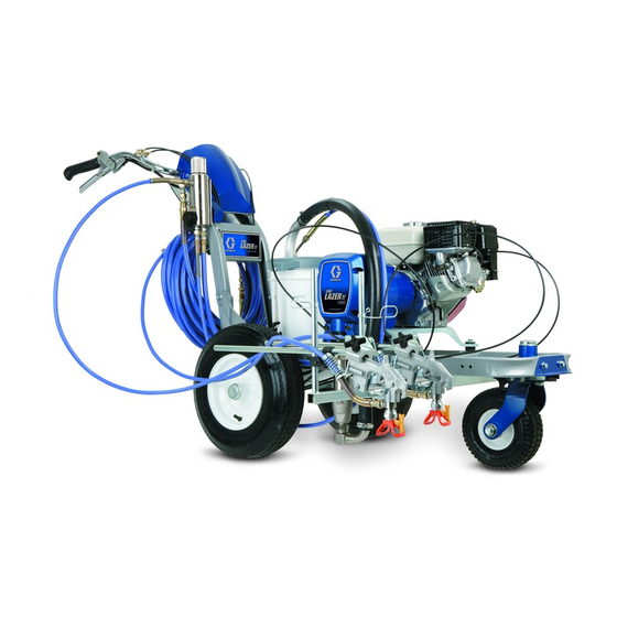
IV 3900, 5900 Auto-Layout
Airless Line Stripers
For application of line striping materials.
3300 psi (22.8 MPa, 228 bar) Maximum Working Pressure
Important Safety Instructions
Read all warnings and instructions in this manual.
Save these instructions.
See page 2 for model information.
Chinese Patent ZL03802251.6
U.S. Patent 6,913,417
U.S. Patent 7,303,155
312190
310643
309741
309055
312345
312307
Graco Inc. P.O. Box 1441 Minneapolis, MN 55440-1441
Copyright 2007, Graco Inc. is registered to I.S. EN ISO 9001
™
System
312195B
ti10233a
Advertisement
Table of Contents

Related Manuals for Graco LineLazer IV 3900


Summary of Contents for Graco LineLazer IV 3900
- Page 1 See page 2 for model information. Chinese Patent ZL03802251.6 U.S. Patent 6,913,417 U.S. Patent 7,303,155 312190 310643 309741 309055 312345 312307 ti10233a Graco Inc. P.O. Box 1441 Minneapolis, MN 55440-1441 Copyright 2007, Graco Inc. is registered to I.S. EN ISO 9001...
-
Page 2: Table Of Contents
Models Contents Engine ........16 Pressure Control. -
Page 3: Warnings
Warnings Warnings The following warnings are for the setup, use, grounding, maintenance, and repair of this equipment. The exclama- tion point symbol alerts you to a general warning and the hazard symbol refers to procedure-specific risk. Refer back to these warnings. Additional, product-specific warnings may be found throughout the body of this manual where applicable. - Page 4 Warnings WARNING EQUIPMENT MISUSE HAZARD Misuse can cause death or serious injury. • Do not operate the unit when fatigued or under the influence of drugs or alcohol. • Do not exceed the maximum working pressure or temperature rating of the lowest rated system component.
-
Page 5: Tip Selection
Tip Selection Tip Selection (cm) (cm) (cm) (cm) ✔ LL5213* 2 (5) ✔ LL5215* 2 (5) ✔ LL5217 4 (10) ✔ LL5219 4 (10) ✔ LL5315* 4 (10) ✔ LL5317 4 (10) ✔ LL5319 4 (10) ✔ LL5321 4 (10) ✔... -
Page 6: Maintenance
Maintenance Maintenance Pressure Relief Procedure AFTER THE FIRST 20 HOURS OF OPERATION: Drain engine oil and refill with clean oil. Reference Honda Engines Owner's Manual for correct oil viscosity. WEEKLY: Remove air filter cover and clean element. Replace element, if necessary. If operating in an unusu- ally dusty environment: check filter daily and replace, if 1. -
Page 7: Troubleshooting
Disconnect clutch wires from control board and measure resistance across clutch coil. At 70° F, the resistance must be between 1.2 +0.2 ohms (LineLazer IV 3900); 1.7 +0.2 ohms (LineLazer IV 5900); if not, replace pinion housing. Have pressure control checked by authorized Graco dealer. - Page 8 Troubleshooting Problem Cause Solution Pump output is low. Strainer (34f) is clogged. Clean strainer. Piston ball is not seating. Service piston ball. See pump manual. Piston packings are worn or damaged. Replace packings. See pump manual. O-ring in pump is worn or damaged. Replace o-ring.
- Page 9 Troubleshooting Problem Cause Solution Clutch squeaks each time Clutch surfaces are not matched to each other Clutch surfaces need to wear into each other. clutch engages. when new and may cause noise. Noise will dissipate after a day of run time. High engine speed at no Misadjusted throttle setting.
-
Page 10: Auto-Layout Can Actuator Adjustment
Auto-Layout Can Actuator Adjustment Auto-Layout Can Actuator Adjustment Adjustments Carefully tighten screws. Verify gap. The can actuator is set at the factory. If the dot size is not as desired, do the coarse and/or fine adjustments. Coarse Adjustment Locate four screws on side of holder base. ti10073a Fine Adjustment If coarse adjustment did not achieve desired dot size,... -
Page 11: Bearing Housing And Connecting Rod
1. Evenly lubricate inside of bronze bearing (C) in bear- ing housing (22) with high-quality motor oil. Liberally LineLazer IV 3900: Torque to 200 in-lb (22.6 N•m). LineLazer IV 5900: Torque to 25 ft-lb (34 N•m). pack top roller bearing (E), lower bearing (D) inside TI6395A connecting rod assembly (26) with bearing grease. -
Page 12: Drive Housing
Bearing Housing and Connecting Rod procedure may also come out. on page 11. 178 24g 24h LineLazer IV 3900: Torque to 200 in-lb (22.6 N•m). LineLazer IV 5900: Torque to 25 ft-lb (34 N•m). Apply remaining grease to these areas. TI6396a... -
Page 13: Pinion Assembly/Clutch Armature/Clamp
Pinion Assembly/Clutch Armature/Clamp Pinion Assembly/Clutch Armature/Clamp Pinion Assembly/Clutch Armature Removal Pinion Assembly If pinion assembly (25) is not removed from clutch hous- ing (85), do steps 1 through 3. Otherwise, start at 4. TI5481b TI5987c 1. Remove drive housing, page 12. 2. - Page 14 Face of clutch housing. 6. F . 6. Check o-ring (25c) and replace if missing or LineLazer IV 3900: 2.55 +/- .010 in. (64.77 +/- 0.25 mm). damaged. LineLazer IV 5900: 2.61 +/- .010 in. (66.29 +/- 0.25 mm) 7. Tap pinion shaft (25d) in with plastic mallet.
-
Page 15: Clutch Housing
Clutch Housing Clutch Housing Removal 1. F . 10. Remove four cap screws (186) and lock washers (188) which hold clutch housing (85) to engine. 2. Remove screw (177) from under mounting plate (96). 3. Pull off clutch housing (85). Installation 1. -
Page 16: Engine
Engine Engine Removal 1. Remove Pinion Assembly/Clutch Arma- Engine ture/Clamp and Clutch Housing. See pages 13 - 15. 2. F . 12. Remove junction box (226). 3. F . 11. Disconnect all necessary wiring. 4. F . 12. Remove screw (177). Remove two screws (117), locknuts (118), and ground conductor (223, 260) from base of engine (185). -
Page 17: Pressure Control
Pressure Control Pressure Control On/Off Switch 4. Press locking tab on ON/OFF switch connector (B) and disconnect from control board. Note: A complete wiring diagram is on page 34. 5. Press in on two retaining tabs on each side of ON/OFF switch and remove switch. - Page 18 Pressure Control Control Board Installation 1. F . 13. Install o-ring (217) and pressure control transducer (216) in filter manifold (40). Torque to Removal 35-45 ft-lb. 2. Connect transducer lead (C) to control board (15d). 3. Install control cover (31) with two screws (125). 1.
-
Page 19: Trigger Sensor Adjustment
Trigger Sensor Adjustment Engine Stop Switch Note: A complete wiring diagram is on page 34. Removal 4. Press in on two retaining tabs on each side of ENGINE STOP switch and remove switch. Installation 1. Install ENGINE STOP switch (15f) so tabs of switch snap into place on inside of pressure control hous- 1. -
Page 20: Control Board Diagnostics
Sprayer stops. Engine High clutch current. 1. Check clutch connections. Clean contacts. is running. 2. Measure 1.2 +0.2 Ohms (LineLazer IV 3900); ti6318a 1.7 +0.2 Ohms (LineLazer IV 5900) across clutch field at 70°F. 3. Replace clutch field assembly. -
Page 21: Displacement Pump
. 17. Loosen locknut by hitting firmly with a 20 oz (maximum) hammer. Unscrew pump. TI7673b . 19 4. F . 20. Fill packing nut with Graco TSL until fluid flows onto the top of seal. TI7673b . 17 TI7677b 7. -
Page 22: Parts
Parts Parts LineLazer IV Page 32 Page 26 Page 30 Page 28 Sheet 1 of 7 Page 31 Page 24 ti10062a 312195B... -
Page 23: Parts - Drive And Pinion Housing Assemblies
Ref No. 25: Pinion Housing Assembly 287463 for LineLazer IV 3900; Pinion Housing Assembly 287465 for LineLazer IV 5900 Ref No. 24: Drive Housing Assembly 287467 for LineLazer IV 3900; Drive Housing Assembly 287469 for Part Description LineLazer IV 5900... - Page 24 Parts - Drive and Pinion Housing Assemblies LineLazer IV Auto-Layout System Sheet 3 of 7 TI7495b 312195B...
- Page 25 Parts - Drive and Pinion Housing Assemblies LineLazer IV Auto-Layout System Part Description Part Description 110837 SCREW, flange, hex 237686 WIRE, ground assembly w/ clamp 255162 WHEEL, pneumatic 245225 HOSE, cpld, 3/8 in. x 50 111040 NUT, lock, insert, nylock, 5/16 245798 HOSE, cpld, 1/4 in.
- Page 26 Parts - Drive and Pinion Housing Assemblies LineLazer IV Auto-Layout System Models 253920, 253921 Ref 25, page 23 Ref 24, page 23 ti6405d 175 172 34 (Detail E) Ref 16, page 24 Detail E (12) Sheet 4 of 7 TI6405c 312195B...
- Page 27 Parts - Drive and Pinion Housing Assemblies LineLazer IV Auto-Layout System Part Description Part Description 108842 SCREW, cap, hex hd 277069 PUMP, displacement, (3900) 118444 SCREW, mach, slot hex wash hd 277070 PUMP, displacement, (5900) 100214 WASHER,(3900) 287714 HOUSING, bearing (3900) 106115 WASHER, (5900) 287715 HOUSING, bearing (5900) 119426 SCREW, mach, hex washer hd, (3900) 12...
- Page 28 Parts - Drive and Pinion Housing Assemblies LineLazer IV Swivel Wheel Assembly 240719 Models 253920 and 253921 Ref 141 (page 24) Ref 16 (page 24) Ref 141 Ref 6 (Detail D) Detail D Install washers (130) concave surface to inside. Sheet 5 of 7 TI6404b 312195B...
- Page 29 Parts - Drive and Pinion Housing Assemblies LineLazer IV Swivel Wheel Assembly 240719 65133 Part Description Part Description 119563 SPRING, belleville 240942 SHAFT, fork 113471 SCREW, cap, hex hd 240991 BRACKET, caster, front 132* 113484 SEAL 15G952 BRACKET 133* 113485 BEARING 181818 KNOB 113962 WASHER 193528 ARM, detent...
- Page 30 Parts - Drive and Pinion Housing Assemblies LineLazer IV Auto-Layout System Models 253920 and 253921 136a Ref 14 ti6494a Ref 144 (page 24) 227 Ref 161 Torque to 90 - 110 in-lb TI6497a Torque to 10 - 20 in-lb Sheet 6 of 7 312195B...
- Page 31 Parts - Drive and Pinion Housing Assemblies LineLazer IV Auto-Layout System Part Description Part Description 119648 SCREW, mch, trs hd, cross recess 224052 BRACKET, support gun 101566 NUT, lock 248157 GUN, flex, basic 111145 KNOB, pronged 287570 HOLDER ASSEMBLY, gun 111017 BEARING, flange 287569 HOLDER, gun 126* 112381 SCREW, mach, pan head...
- Page 32 Parts - Drive and Pinion Housing Assemblies LineLazer IV Auto-Layout System Models 253920 and 253921 part of 15h Ref 27 Ref 13 Ref 100 TI6399c Sheet 7 0f 7 Ref 14 312195B...
- Page 33 196181 FITTING, nipple 116752 SWITCH, rocker 104813 PLUG, pipe 241443 POTENTIOMETER KIT 115642 BUSHING, relief, strain 15B804 LABEL, Graco logo 15J087 HARNESS 111839 SCREW, mach, pnh, sems 15F814 GASKET, handle 120743 SCREW, mach, pnh, sems 117501 SCREW, mach, slot hex wash hd...
-
Page 34: Auto-Layout System Wiring Diagram
Auto-Layout System Wiring Diagram Auto-Layout System Wiring Diagram 119579 (ref. 268) WHITE/BLACK 1. BLUE 2. BLACK 3. WHITE/BLUE 4. BLACK/WHITE ti10235a . 21 312195B... -
Page 35: Technical Data
Maximum delivery LineLazer IV 3900 ......1.15 gpm (4.4 liter/min) LineLazer IV 5900 ...... -
Page 36: Dimensions
Dimensions Dimensions LineLazer IV 3900 Auto-Layout System Model 253920, 255151 Striper Weight (dry, without packaging) ..212 lb (96 kg) Height..... . . 40 in. (101.6 cm) Length . - Page 37 Dimensions 312195B...
-
Page 38: Warranty
With the exception of any special, extended, or limited warranty published by Graco, Graco will, for a period of twelve months from the date of sale, repair or replace any part of the equipment determined by Graco to be defective.
Need help?
Do you have a question about the LineLazer IV 3900 and is the answer not in the manual?
Questions and answers