Table of Contents
Advertisement
Quick Links
Operation, Parts
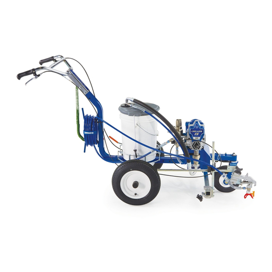
LineLazer
Line Striper
For the application of line striping materials. For professional use only. Not approved
for use in explosive atmospheres or hazardous (classified) locations.
Models: 25U546, 25U547, 25U548
3300 psi (228 bar, 22.8 MPa) Maximum Working Pressure
Important Safety Instructions
Read all warnings and instructions in this manual and related
manuals before using the equipment. Be familiar with the controls
and the proper usage of the equipment. Save these instructions.
Related Manuals
Manual
Description
311254
Gun
334599
Pump
Use only genuine Graco replacement parts.
The use of non-Graco replacement parts may void warranty.
®
ES 500 Airless
3A9031A
EN
Advertisement
Table of Contents

Related Manuals for Graco LineLazer ES 500


Summary of Contents for Graco LineLazer ES 500
- Page 1 Be familiar with the controls and the proper usage of the equipment. Save these instructions. Related Manuals Manual Description 311254 334599 Pump Use only genuine Graco replacement parts. The use of non-Graco replacement parts may void warranty.
-
Page 2: Table Of Contents
California Proposition 65 ........43 Graco Standard Warranty ........44 Graco Information . -
Page 3: Models
120 USA/CA 25U547 54 EMEA/UK 230 EMEA/UK 25U548 54 ANZ/AP 230 ANZ/AP ® ® The LineLazer ES 500 is compatible with the following DEWALT FLEXVOLT 54V and 60V batteries: • DCB606 - 60V/2ah (20V/6ah) • DCB546 - 54V/2ah (18V/6ah) •... -
Page 4: Important Grounding Information
Important Grounding Information Important Grounding Information The following information is intended to help you understand when to use the grounding wire and clamp provided with your striper. It is required when flushing or cleaning with flammable materials. Please read the information on the material container label to determine if it is flammable. Ask for a Safety Data Sheet (SDS) from your supplier. -
Page 5: Warnings
Use Graco conductive or grounded high-pressure airless paint sprayer hoses. - Page 6 Check hoses and parts for signs of damage. Replace any damaged hoses or parts. • This system is capable of producing 3300 psi (228 bar, 22.8 MPa). Use Graco parts or accessories that are rated a minimum of 3300 psi (228 bar, 22.8 MPa).
- Page 7 Warnings WARNING PRESSURIZED ALUMINUM PARTS HAZARD Use of fluids that are incompatible with aluminum in pressurized equipment can cause serious chemical reaction and equipment rupture. Failure to follow this warning can result in death, serious injury, or property damage. • Do not use 1,1,1-trichloroethane, methylene chloride, other halogenated hydrocarbon solvents or fluids containing such solvents.
-
Page 8: Component Identification
Component Identification Component Identification 11 Battery ON/OFF Switch 12 Park Brake Pressure Control 13 Front Wheel Lock/Unlock Prime/Spray Valve 14 Adjustable Pail Holder Spray Gun Trigger 15 Adjustable Handle Filter 16 Serial Label (on front side) Spray Gun Trigger Lock 17 Pressure Gauge Siphon Hose 18 Gun Retainer Knob... -
Page 9: Grounding Instructions
Grounding Instructions Grounding Instructions (Flammable Flushing and Cleaning Materials) Pails Flammable and oil-based materials: follow local codes and regulations. Use only conductive metal pails, placed on a grounded The equipment must be grounded to reduce the surface such as concrete. risk of static sparking. -
Page 10: Pressure Relief Procedure
Pressure Relief Procedure Pressure Relief Procedure Turn pressure control to lowest setting. Follow the Pressure Relief Disengage the trigger lock. Procedure whenever you see this symbol. This equipment stays pressurized until pressure is manually relieved. To help prevent serious injury from pressurized fluid, such as skin injection, splashed fluid and moving parts, follow the Pressure ti25230a... -
Page 11: Trigger Lock
Pressure Relief Procedure Trigger Lock Put drain tube in a pail. Turn prime valve down. Leave prime valve in down (drain) position until you are ready to spray Always engage the trigger lock when sprayer again. is stopped to prevent the gun from being triggered accidentally by hand or if dropped or bumped. -
Page 12: Setup
Setup Setup Front Wheel Alignment When unpacking sprayer for the first time or after long term storage perform setup procedure. Loosen cap screw. Fill throat packing nut with TSL. ti6392a Position front wheel left or right, as necessary, to straighten alignment. Tighten cap screw. -
Page 13: Spray Tip Installation
Setup Spray Tip Installation Spray tip must be pushed all the way into the tip guard. Turn spray tip to push down. To avoid serious injury from skin injection, do not put your hand in front of the Spray Tip when installing or removing the Spray Tip and Spray Tip Guard. -
Page 14: Battery Installation And Removal
Setup Battery Installation and Removal Always start with a fully charged Battery. Install battery by aligning the battery Do not splash or immerse Battery or pack with the rails inside the sprayer and charger in water. See Battery and charger sliding it in until the battery pack is firmly information shipped with the sprayer. -
Page 15: Startup
Startup Startup Flush Storage Fluid This striper arrives from the factory with a small amount of test material in the system. It is important that you flush this material from the striper before using it for the first time. When flushing with flammable Prime/Spray Valve materials, follow Grounding Instructions, page 9. - Page 16 Startup Place drain tube in a grounded Place Prime/Spray valve in PRIME waste pail. position. Install battery, see Battery Installation and Removal, page 14. Align setting indicator with a low setting on Pressure Control Knob. Submerge siphon tube in a grounded pail partially filled with water or flushing fluid.
-
Page 17: Fill Pump
Startup Fill Pump Increase pressure 1/2 turn to start motor. Allow paint or other material to circulate through sprayer until material Move siphon tube to paint pail and flows out of the drain tube. submerge siphon tube in paint. 10. When sprayer starts pumping, flush fluid and air bubbles will be purged from system. -
Page 18: Fill Gun And Hose
Startup Fill Gun and Hose Trigger gun into waste pail until only paint comes out of the gun. Hold gun against a grounded waste pail. Release trigger. Engage trigger lock. Point gun into waste pail. Transfer drain tube to paint pail and clip Loosen gun retainer knob and to siphon tube. -
Page 19: How To Spray
How to Spray How to Spray Install Gun Position gun left/right. Insert gun into gun holder with hose guard pressed against the holder assembly bracket. Tighten gun into clamp. Right-side gun position: Place gun and related hardware on right-hand side. Position Gun Position gun up/down and forward/reverse. -
Page 20: Paint Stripe Width
How to Spray Paint Stripe Width For Curb Position, place gun at 45° angle. Adjust gun up or down to change paint stripe width. If desired width cannot be attained, change tip. Refer to Component Identification, page 8 for proper tip for application. ti30098a ti30304a For Gun Arc Spray Position, place gun... -
Page 21: Stencil Spraying
How to Spray Stencil Spraying Fan Width Fan width is the size of the spray pattern, Loosen gun retainer knob. which determines the area covered with Remove gun from holder. each stroke. Trigger spray gun over stencil pattern. Hints: Return gun to holder. •... -
Page 22: Tip Selection
Tip Selection Tip Selection (cm) (cm) (cm) (cm) LL5213* 2 (5) ✓ LL5215* 2 (5) ✓ LL5217 4 (10) ✓ LL5219 4 (10) ✓ LL5315 4 (10) ✓ LL5317 4 (10) ✓ LL5319 4 (10) ✓ LL5321 4 (10) ✓ LL5323 4 (10) ✓... -
Page 23: Clear Tip Clog
Clear Tip Clog Clear Tip Clog Release trigger. Engage trigger lock. Engage trigger lock. Return Spray Tip to Rotate Spray Tip. Disengage trigger original position. Disengage trigger lock lock. Trigger gun at waste area to clear and continue spraying. clog. 3A9031A... -
Page 24: Cleanup
Cleanup Cleanup Unscrew cap, remove filter. Assemble without filter. Clean filter. To avoid serious injury from fire and explosion when using flammable materials: • Do not spray solvents through the spray tip. Always remove tip guard and spray tip before flushing. Clean tip guard and spray tip in a bucket of compatible solvent. - Page 25 Cleanup Install battery, see Battery Installation 13. Gradually turn pressure control up until and Removal, page 14. motor begins to drive pump. Trigger gun until flushing fluid appears. 10. Switch ON/OFF switch to ON position. Button is illuminated when ON. 11.
- Page 26 Cleanup 15. Open prime valve and allow flushing fluid to circulate for 20 seconds to clean NOTICE drain tube. If flushing with water, do not leave water in striper for extended periods. Flush again with Pump Armor and leave protective coating in the striper to prevent freezing or corrosion and to increase striper life.
- Page 27 Cleanup 20. Clean Rac Tip, Rac Guard, and gasket with a soft bristle brush to prevent part failure due to dried materials. Assemble parts and attach loosely onto gun. 21. Wipe striper, hose, and gun with a rag soaked in water or mineral spirits. 3A9031A...
-
Page 28: Cleaning And Flushing Fluid Compatibilty
Cleaning and Flushing Fluid Compatibility Cleaning and Flushing Fluid Compatibility When flushing with flammable materials, always follow Grounding Instructions, page 9. If you’re going to: Flush with: Prime with: Clean with: Store with: Spray with new striper or Compatible fluid such Compatible paint, Compatible Mineral spirits... -
Page 29: Maintenance
Maintenance Maintenance Routine maintenance is important to ensure proper operation of your sprayer. Maintenance includes performing routine actions which keep your sprayer in operation and prevents trouble in the future. Activity Interval Inspect/clean sprayer filter, fluid inlet strainer, and gun Daily or each time you spray filter. -
Page 30: Troubleshooting
Troubleshooting Troubleshooting Mechanical/Fluid Flow Follow Pressure Relief Procedure, Check all possible problems and causes page 10, before checking or repairing. before disassembling the unit. What to Check What to Do If check is OK, go to next When check is not OK, Problem check refer to this column... - Page 31 Troubleshooting What to Check What to Do If check is OK, go to next When check is not OK, Problem check refer to this column Pump output is low Pump rod damage. Repair pump. See pump manual. Low stall pressure (pressure Turn pressure knob fully setting too low).
- Page 32 Troubleshooting What to Check What to Do If check is OK, go to next When check is not OK, Problem check refer to this column Pump is difficult to prime Air in pump or hose. Check and tighten all fluid connections.
-
Page 33: Electrical
Check motor leads. Make certain terminals are clean and firmly connected. Check all wiring harnesses for Repair wires or bring to Graco pinched or severed wires certified repair shop. (power switch, motor, pressure control). Sprayer will not shut off after Check pressure control. -
Page 34: Parts
Parts Parts ES 500 Airless Line Striper Parts Ref. Torque Ref. Torque Ref. Torque 80-90 in-lbs (9-10.2 25-35 in-lbs (2.8-4 N•m) 17-23 ft-lbs (23-31 N•m) N•m) 23-27 in-lbs (2.6-3.1 190-210 in-lbs (21.5-28.7 N•m) N•m) 3A9031A... - Page 35 Parts ES 500 Airless Line Striper Parts List Ref. Part Description Ref. Part Description 17N536 HOLDER, bucket 19D570 FRAME, LL 24Z284 BAR, handle, LL 119542 WHEEL, small 113665 SCREW, cap, hex hd 119543 WHEEL, large 114802 WIRE, stop 15F127 FORK, painted 119554 NUT, lock, nylon, thin pattern 119532...
- Page 36 Parts Motor Module Parts Ref. Torque Ref. Torque Ref. Torque 140-160 in-lbs. 10-20 in-lbs (1.13-2.26 (15.8-18.1 N•m) N•m) 23-27 in-lbs (2.6-3.1 25-35 in-lbs (2.8-4 N•m) N•m) 8-10 in-lbs (0.9-1.13 40-50 in-lbs (4.5-5.6 N•m) N•m) 3A9031A...
- Page 37 Parts Motor Module Parts List Part Description Qty. Ref. Part Description Qty. Ref. 19D571 SHELF, motor 107434 BEARING, thrust 128795 SCREW, mach, pan hd., torx 20A450 GASKET 19D553 BRACKET, adapter, ES 500 20A052 SPRING BUTTON, 102040 NUT, lock assembly 17C483 COVER, pump rod 115498 SCREW, mch, slot/hex,...
- Page 38 Parts Filter Manifold Parts Ref. Torque Ref. Torque Ref. Torque Ref. Torque 140-160 in-lbs. 130-140 in-lbs (14.7-16.9 48-72 in-lbs (5.4-8.1 (15.8-18.1 N•m) N•m) N•m) 3A9031A...
- Page 39 Parts Filter Manifold Parts List Ref. Part Description Qty. Ref. Part Description Qty. 196181 NIPPLE, (1/4 npsm x 1/4 117828 PACKING, o-ring npt) 111600 PIN, grooved 15E022 SEAT, valve 277364 GASKET, seat, valve 187625 HANDLE, valve, drain 17C590 MANIFOLD, fluid 17D294 SPACER, manifold FILTER, fluid (tall...
- Page 40 Parts Gun Arm Parts Part Description Part Description 188135 GUIDE, cable 119664 BEARING, sleeve LL5317 TIP, spray, striping, 248157 GUN, flex includes 157 15F216 HOLDER, gun LL5419 TIP, spray, striping, 20a* 15F750 KNOB, holder, gun 20b* 15F214 LEVER, actuator includes 157 20c* 15F209 STUD, pull trigger 210* 17H720 STRAP, tie, 5 in.
-
Page 41: Wiring Diagram
Wiring Diagram Wiring Diagram 3A9031A... -
Page 42: Technical Specifications
Technical Specifications Technical Specifications LineLazer ES 500 Airless Line Striper Metric Sprayer Maximum fluid working pressure 3300 psi 228 bar, 22.8 MPa Maximum delivery 0.47 gpm 1.8 lpm Maximum tip size 1 gun with 0.021 in. tip Inlet paint strainer... -
Page 43: California Proposition 65
California Proposition 65 California Proposition 65 CALIFORNIA RESIDENTS WARNING: Cancer and reproductive harm – www.P65warnings.ca.gov. 3A9031A... -
Page 44: Graco Standard Warranty
With the exception of any special, extended, or limited warranty published by Graco, Graco will, for a period of twelve months from the date of sale, repair or replace any part of the equipment determined by Graco to be defective. This warranty applies only when the equipment is installed, operated and maintained in accordance with Graco’s written recommendations. -
Page 45: Graco Information
Graco Information Graco Information For the latest information about Graco products, visit www.graco.com. For patent information, see www.graco.com/patents. TO PLACE AN ORDER, contact your Graco distributor or call 1-800-690-2894 to identify the nearest distributor. 3A9031A... - Page 46 3A9031A...
- Page 47 3A9031A...
- Page 48 All written and visual data contained in this document reflects the latest product information available at the time of publication. Graco reserves the right to make changes at any time without notice. Original instructions. This manual contains English. MM 3A9031...
Need help?
Do you have a question about the LineLazer ES 500 and is the answer not in the manual?
Questions and answers