Table of Contents
Advertisement
Quick Links
Operation, Repair, Parts
™
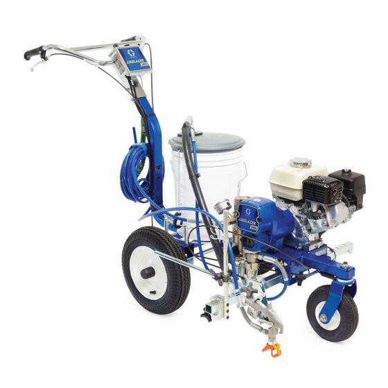
LineLazer
For the application of line striping materials. For professional use only. For outdoor use
only. Not approved for use in explosive atmospheres or hazardous locations.
Models: 25M224, 25P341 (China Model Only)
3300 psi (22.8 MPa, 228 bar) Maximum Operating Pressure
Important Safety Instructions
Read all warnings and instructions in this manual, related manuals, and on the
equipment. Be familiar with the controls and the proper usage of the equipment.
Save these instructions.
Related Manuals:
311254
Gun
309250
Pump
3400 Airless Line Striper
ti30298a
3A4587D
EN
Advertisement
Table of Contents

Related Manuals for Graco 25M224


Summary of Contents for Graco 25M224
- Page 1 For the application of line striping materials. For professional use only. For outdoor use only. Not approved for use in explosive atmospheres or hazardous locations. Models: 25M224, 25P341 (China Model Only) 3300 psi (22.8 MPa, 228 bar) Maximum Operating Pressure...
-
Page 2: Table Of Contents
Flushing Recommendations ....21 25M224 ....... 34 Troubleshooting . -
Page 3: Warnings
• Check hoses and parts for signs of damage. Replace any damaged hoses or parts. • This system is capable of producing 3300 psi. Use Graco replacement parts or accessories that are rated a minimum of 3300 psi. - Page 4 Warnings EQUIPMENT MISUSE HAZARD Misuse can cause death or serious injury. • Do not operate the unit when fatigued or under the influence of drugs or alcohol. • Do not exceed the maximum working pressure or temperature rating of the lowest rated system component.
- Page 5 Warnings PERSONAL PROTECTIVE EQUIPMENT Wear appropriate protective equipment when in the work area to help prevent serious injury, including eye injury, hearing loss, inhalation of toxic fumes, and burns. This protective equipment includes but is not limited to: • Protective eyewear, and hearing protection. •...
-
Page 6: Tip Selection
Tip Selection Tip Selection (cm) (cm) (cm) (cm) LL5213* 2 (5) LL5215* 2 (5) LL5217 4 (10) LL5219 4 (10) LL5315 4 (10) LL5317 4 (10) LL5319 4 (10) LL5321 4 (10) LL5323 ... -
Page 7: Component Identification
Component Identification Component Identification ti30299a PRIME SPRAY Engine ON/OFF Switch Pump ON/OFF Switch Throttle Pressure Control Drain Hose Spray Gun Trigger Suction Tube Filter Parking Brake Pressure Gauge Adjustable Handle Prime Valve Front Wheel Unlock/Lock Pump Adjustable Pail Holder Trigger Lock Serial ID Choke 3A4587D Operation, Repair, Parts... -
Page 8: Grounding Procedure
Grounding Procedure (For Flammable Materials Only) Grounding Procedure Do not place pail on a non-conductive surface such as paper or cardboard which interrupts grounding continuity. (For Flammable Materials Only) This equipment must be grounded to reduce the risk of static sparking. Static sparking can cause fumes to ignite or explode. -
Page 9: Pressure Relief Procedure
Pressure Relief Procedure Pressure Relief Procedure Follow the Pressure Relief Procedure 3. Turn pressure to lowest setting. Trigger gun to relieve pressure. whenever you see this symbol. This equipment stays pressurized until pressure is ti30106a manually relieved. To help prevent serious injury 4. -
Page 10: Front Wheel Alignment
Pressure Relief Procedure DAILY: Check engine oil level and fill as necessary. SPARK PLUG: Use only BPR6ES (NGK) or W20EPR-U (NIPPONDENSO) plug. Gap plug to 0.028 DAILY: Check hose for wear and damage. to 0.031 in. (0.7 to 0.8 mm). Use spark plug wrench DAILY: Check gun safety for proper operation. -
Page 11: Operation
Operation Operation Setup 3. Check engine oil level. See Honda engine manual. The equipment must be grounded to reduce the risk of static sparking. Static sparking can cause fumes to ignite or explode. Grounding provides an escape wire ti27610a for the electric current. 4. -
Page 12: Startup
Operation Startup 4. Turn pressure control counterclockwise to lowest pressure. 1. Perform Pressure Relief Procedure. See Grounding Procedure (For Flammable Materials Only), page ti6256b 2. Place siphon tube set in grounded metal pail partially 5. Set pump switch to OFF. filled with flushing fluid. - Page 13 Operation c. Set throttle to fast. NOTICE Do not run pump without fluid flow. Damage to packings can occur. 7. Set pump switch to ON. Increase pressure enough to start pump. Allow fluid to circulate for 15 seconds. ti5250a d. Set engine switch to ON. ti30076a 8.
-
Page 14: Rac Tip And Guard Assembly
Operation Rac Tip and Guard Assembly High-pressure spray is able to inject toxins into the body and cause serious bodily injury. Do not stop To avoid serious injury from skin injection do not put leaks with hand or rag. your hand in front of the spray tip when installing or removing the spray tip and tip guard. -
Page 15: Gun Placement
Gun Placement Gun Placement Install Gun 3. Position gun left/right. 1. Insert gun into gun holder with hose guard pressed against the holder assembly bracket. Tighten gun into clamp. ti30301a a. Right-side gun position: Place gun and related hardware on right-hand side. ti30093a Position Gun 2. - Page 16 Gun Placement b. Left-side gun position: Place gun and related 5. For Gun Arc Spray Position, place gun at rear of striper. Rear position improves arc quality. hardware on left-hand side. ti30099a NOTE: Verify that the gun can still be triggered and that the trigger lock can still be engaged after installation.
-
Page 17: Paint Stripe Width
Paint Stripe Width Paint Stripe Width 1. Adjust gun up or down to change paint stripe width. 2. Trigger gun and spray test pattern. Slowly adjust If desired width can’t be attained, change tip. pressure to eliminate heavy edges. Use smaller tip size if pressure adjustment can not eliminate heavy edges. -
Page 18: Clean-Up
Clean-up Clean-up 4. Clean gun filter, Rac Guard and Rac Tip in flushing fluid. See Flushing Recommendations, page 21. 1. Perform Pressure Relief Procedure. See Pressure Relief Procedure, page 8. 2. Remove Rac Guard and Rac Tip. ti30488a 5. Remove siphon tube set from paint and place in flushing fluid. - Page 19 Clean-up 7. Close prime valve. 10. Move gun to flushing pail, hold gun against pail, trig- ger gun to thoroughly flush system. Release trigger and engage trigger lock. ti30114a 8. Hold gun against paint pail. Disengage gun trigger lock. ti30117a 11.
- Page 20 Clean-up 14. Close prime valve. Trigger gun into flushing pail to NOTICE purge fluid from hose. Open prime valve. Do not run pump without fluid flow. Damage to packings can occur. 12. Raise siphon tube above flushing fluid and run striper for 15 to 30 seconds to drain fluid.
-
Page 21: Flushing Recommendations
Flushing Recommendations Flushing Recommendations If you are going to: Flush with: Prime with: Clean with: Store with: Compatible paint, Compatible solvent such Spray with new sprayer or Compatible solvent such as Mineral such as water-base as water or mineral sprayer that has been stored water or mineral spirits spirits or oil-base... -
Page 22: Troubleshooting
At 70° F, the resistance must be between 1.2+0.2 ohms; if not, replace pinion housing. Have pressure control checked by authorized Graco dealer. Clutch is worn, damaged, or incor- Adjust or replace clutch. Page 27. rectly positioned Pinion assembly is worn or damaged Repair or replace pinion assembly. - Page 23 Troubleshooting Problem Cause Solution Pump output is low Strainer (56) is clogged Clean strainer. Piston ball (206) is not seating Service piston ball. Manual 309250. Piston packings are worn or damaged Replace packings. Manual 309250. O-ring (227) in pump is worn or damaged Replace o-ring. Manual 309250. Intake valve ball is not seating properly Clean intake valve.
-
Page 24: Displacement Pump
Displacement Pump Displacement Pump Removal 5. Loosen jam nut by hitting firmly with a hammer. Unscrew pump. 1. Stop pump with piston rod (201) in its lowest position. 2. Perform Pressure Relief Procedure, page 9. 3. Loosen two screws (108) and remove pump rod cover (107). -
Page 25: Installation
Displacement Pump Installation 3. Screw jam nut down onto pump until nut stops. Screw pump up into drive housing until top threads of pump are flush with drive housing face. Back off pump and jam nut to align pump outlet to side. Tighten jam nut by hand, then tap 1/8 to 1/4 turn with a 20 oz (maximum) hammer to approximately If pin works loose, parts could break off due to force... -
Page 26: Drive Housing And Connecting Rod
Drive Housing and Connecting Rod Drive Housing and Connecting Rod Removal NOTICE DO NOT use drive housing screws (34) to align or seat bearing housing with drive housing. Align these parts with locating pins, to avoid premature bearing wear. 7. Install screws (34) in drive housing. 1. -
Page 27: Pinion Assembly/Clutch Armature/Clamp
Pinion Assembly/Clutch Armature/Clamp Pinion Assembly/Clutch Armature/Clamp Pinion Assembly/Clutch 6. Remove four screws (42) and lock washers (35). Install two screws in threaded holes (E) in rotor. Armature Removal Alternately tighten screws until rotor comes off. Pinion Assembly If pinion assembly (44) is not removed from clutch hous- ing (45), do 1. -
Page 28: Installation
Pinion Assembly/Clutch Armature/Clamp Clutch Armature Pinion Assembly 9. Use an impact wrench or wedge something 6. Install o-ring (44e). between clutch armature (39) and clutch housing to 7. Tap pinion shaft (44c) in with plastic mallet. hold engine shaft during removal. 8. -
Page 29: Clamp Removal
Pinion Assembly/Clutch Armature/Clamp Clamp Removal Clamp Installation 1. Install engine shaft key (37) 1. Remove engine. See Engine Removal, page 30. 2. Tap clamp (38) onto engine shaft (A). Maintain 2. Drain gasoline from tank according to Honda man- dimension shown note 2. Chamfer must face ual. -
Page 30: Clutch Housing
Clutch Housing Clutch Housing Removal 1. Remove clamp. Do Clamp Removal, page 29. 2. Remove four screws (51) and lock washers (50) which hold clutch housing (45) to engine. 3. Remove screw (145) from under mounting plate. 4. Pull off clutch housing (45). Installation 1. -
Page 31: Pressure Control Transducer
Pressure Control Transducer Pressure Control Transducer Removal Installation 1. Remove two screws (108) and open cover (62a). 1. Install o-ring (99) and transducer (155) in filter hous- ing (67). Torque to 35 - 45 ft-lb. 2. Disconnect transducer (155) lead from control board (62e). -
Page 32: Pressure Control (On/Off Switch)
Pressure Control (On/Off Switch) Pressure Control (On/Off Switch) Removal Installation 1. Install new ON/OFF switch (62d) so tabs of switch 1. Perform Pressure Relief Procedure, page 9. snap into place on inside of cover. 2. Remove two screws (108) and open cover (62a). 2. -
Page 33: Pressure Adjust Potentiometer
Pressure Adjust Potentiometer Pressure Adjust Potentiometer Removal Installation 1. Remove two screws (108) and open cover (62a). 1. Install spacer (62g) on potentiometer (62b). 2. Disconnect potentiometer (62b) lead from control 2. Install potentiometer, shaft nut, lock washer and board (62e). potentiometer knob (62c). -
Page 34: Parts Drawing
Parts Drawing Parts Drawing 25M224 90 149 ti30311a 3A4587D Operation, Repair, Parts... -
Page 35: Parts List - 25M224
Parts List - 25M224 Parts List - 25M224 Ref. Part Description Ref. Part Description 15F047 CONTROL, box 17N510 FRAME, LL 113665 SCREW, cap, hex hd 119542 WHEEL, small 114802 WIRE, stop 119543 WHEEL, large 119554 NUT, lock, nylon, thin pattern... -
Page 36: Parts Drawing
Parts Drawing Parts Drawing ti30312a 3A4587D Operation, Repair, Parts... -
Page 37: Parts List - 25M224
Parts List - 25M224 Parts List - 25M224 Ref. Part Description Ref. Part Description 107434 BEARING, thrust 16D576 LABEL, made in USA 100214 WASHER, lock 246428 PUMP, displacement 108842 SCREW, cap, hex hd 196750 SPRING, retaining 287487 COVER, front, painted... -
Page 38: Parts Drawing And List - Pinion Housing
Parts Drawing and List - Pinion Housing Parts Drawing and List - Pinion Housing Ref No. 44: Pinion Housing Ref. Part Description 287376 PINION HOUSING 287482 KIT, repair, coil 105489 44c* 287485 PINION SHAFT 44d* 113094 RETAINING RING, large 44e* 165295 O-RING, packing * May be ordered separately ti30133a... -
Page 39: Gun Arm Parts
Gun Arm Parts Gun Arm Parts Part Description Part Description 17J407 BRACKET, support gun 248157 GUN, flex 119647 SCREW, cap, socket, flthd 15F216 HOLDER, gun 188135 GUIDE, cable 20a* 15F750 KNOB, holder, gun LL5319 TIP, spray, striping, includes 157 20b* 15F214 LEVER, actuator *17H720 STRAP, tie, 5 in. -
Page 40: Pressure Control/Filter Assembly
Pressure Control/Filter Assembly Pressure Control/Filter Assembly ti30129a ti30134a 3A4587D Operation, Repair, Parts... -
Page 41: Parts List - Pressure Control/Filter Assembly
Parts List - Pressure Control/Filter Assembly Parts List - Pressure Control/Filter Assembly Part Description Part Description 100* 15C972 PIN, grooved 15E748 BRACKET, manifold 101* 224807 BASE, valve 15E991 COVER, control box 102* 239914 VALVE, drain 256219 POTENTIOMETER 103* 117285 O-RING 116167 KNOB, potentiometer 104* 243984... -
Page 42: Pressure Control Wiring Diagram
Pressure Control Wiring Diagram Pressure Control Wiring Diagram CONTROL BOARD CLUTCH BLACK CLUTCH GROUND GREEN/YELOW ON/OFF SWITCH PINK POTENTIOMETER GREEN/YELLOW BLACK TRANSDUCER PINK FROM ENGINE (PINK) FROM CLUTCH HOUSING BLACK FROM CLUTCH HOUSING ti30126a 3A4587D Operation, Repair, Parts... -
Page 43: Technical Data
Technical Data Technical Data LineLazer 3400 (Model 25M224) Metric Honda GX120 engine SAE J1995 @ 3600 rpm 4.0 Horsepower Maximum working pressure 3300 psi 22.8 MPa, 228 bar Maximum delivery 0.75 gpm 2.84 lpm Maximum tip size 1 gun with 0.027 in. tip... -
Page 44: Graco Standard Warranty
With the exception of any special, extended, or limited warranty published by Graco, Graco will, for a period of twelve months from the date of sale, repair or replace any part of the equipment determined by Graco to be defective.
Need help?
Do you have a question about the 25M224 and is the answer not in the manual?
Questions and answers