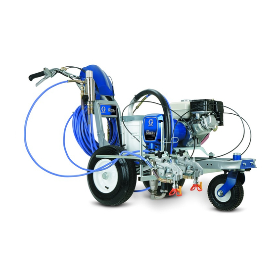
Graco LineLazer IV 3900 Repair And Parts Manual
Airless line stripers
Hide thumbs
Also See for LineLazer IV 3900:
- Operation (54 pages) ,
- Repair parts list manual (38 pages) ,
- Important safety instructions manual (36 pages)
Table of Contents
Advertisement
Quick Links
Repair - Parts
LineLazer™ IV 3900, R300, 5900, and
FieldLazer R300 Airless Line Stripers
3300 psi (22.8 MPa, 228 bar) Maximum Working Pressure
Important Safety Instructions
Read all warnings and instructions in this manual and in LineLazer,
FieldLazer Operation manual. Be familiar with the controls and the
proper usage of the equipment. Save these instructions
311017
312540
310643
311254
309055
311049
- For application of line stripling materials -
311020Y
EN
ti25623a
Advertisement
Table of Contents

Related Manuals for Graco LineLazer IV 3900


Summary of Contents for Graco LineLazer IV 3900
- Page 1 Repair - Parts LineLazer™ IV 3900, R300, 5900, and 311020Y FieldLazer R300 Airless Line Stripers - For application of line stripling materials - 3300 psi (22.8 MPa, 228 bar) Maximum Working Pressure Important Safety Instructions Read all warnings and instructions in this manual and in LineLazer, FieldLazer Operation manual.
-
Page 2: Table Of Contents
Trigger Sensor Adjustment ....19 Graco Standard Warranty ....37... -
Page 3: Models
Models Models 3900 248862 248863 249008 249009 248864 248865 R300 ti6394a 24M605 24M607 5900 248866 248867 249010 ... -
Page 4: Warnings
Warnings Warnings The following warnings are for the setup, use, grounding, maintenance, and repair of this equipment. The exclama- tion point symbol alerts you to a general warning and the hazard symbols refer to procedure-specific risks. When these symbols appear in the body of this manual or on warning labels, refer back to these Warnings. Product-specific hazard symbols and warnings not covered in this section may appear throughout the body of this manual where applicable. - Page 5 Warnings WARNING WARNING WARNING WARNING PRESSURIZED ALUMINUM PARTS HAZARD Use of fluids that are incompatible with aluminum in pressurized equipment can cause serious chemical reaction and equipment rupture. Failure to follow this warning can result in death, serious injury, or property damage. •...
-
Page 6: Tip Selection
Tip Selection Tip Selection (cm) (cm) (cm) (cm) LL5213* 2 (5) LL5215* 2 (5) LL5217 4 (10) LL5219 4 (10) LL5315 4 (10) LL5317 4 (10) LL5319 4 (10) LL5321 4 (10) LL5323 4 (10) ... -
Page 7: Maintenance
Maintenance Maintenance Pressure Relief Procedure DAILY: Check and fill the gas tank. AFTER THE FIRST 20 HOURS OF OPERATION: Follow the Pressure Relief Procedure whenever Drain engine oil and refill with clean oil. Reference you see this symbol. Honda Engines Owner’s Manual for correct oil viscosity. WEEKLY: Remove air filter cover and clean element. -
Page 8: Troubleshooting
Measure resistance across clutch coil. At 70° F, the resistance must be between 1.2 0.2 (LineLazer IV 3900/R300); 1.7 0.2 (LineLazer IV 5900); if not, replace pinion housing. Have pressure control checked by authorized Graco dealer. - Page 9 Troubleshooting Problem Cause Solution Pinion assembly is worn or damaged Repair or replace pinion assembly. Page 13. Pump output is low Strainer (34f) is clogged Clean strainer. Piston ball is not seating Service piston ball. See pump manual. Piston packings are worn or damaged Replace packings.
- Page 10 Troubleshooting Problem Cause Solution Gallon counter not working Broken or disconnected wire Check wires and connections. Replace broken wires. Bad sensor Replace sensor Missing magnet Reposition or replace magnet. Sprayer operates, but display does not Bad connection between control board Remove display and reconnect and display Display damaged...
-
Page 11: Bearing Housing And Connecting Rod
Liberally pack top roller bearing (E), lower bearing (D) inside connecting rod assembly (26) with Pack with bearing grease 114819 bearing grease. LineLazer IV 3900/R300: Torque to 200 in-lb (22.6 N·m) LineLazer V Assemble connecting rod (26) and bearing housing 5900: Torque to 25 ft-lb (22). -
Page 12: Drive Housing
Bearing Housing and Connecting Rod procedures on page 11. ti6396a LineLazer IV 3900/R300: Torque to 200 in-lb (22.6 N·m) LineLazer IV 5900: Torque to 25 ft-lb (34 N·m) Fig. 3 Apply remaining grease to these areas... -
Page 13: Pinion Assembly/Clutch Armature/Clamp
Pinion Assembly/Clutch Armature/Clamp Pinion Assembly/Clutch Armature/Clamp Pinion Assembly Removal If pinion assembly (25) is not removed from clutch hous- ing (85), so 1 through (3). Otherwise, start at 4. Remove drive housing, page. 12. Fig. 12. Remove clip (251) and junction box (226). ti5481b ti5987c Fig. - Page 14 Fig. 9. Loosen two screws (175) on clamp (82). Face of clutch housing Push screwdriver into slot on clamp (82) and 2.55 ± .010 in. (39.37 ± 25 mm); LineLazer IV 3900/R300 remove clamp. Torque to 125 ± .10 in-lb (14 ± 1.1 N·m)
-
Page 15: Clutch Housing
Clutch Housing Clutch Housing Removal Fig. 10. Remove four cap screws (186) and lock washers (188) which hold clutch housing (85) to engine. Remove screw (177) from under mounting plate (96). Pull off clutch housing (85). Installation Fig. 10. Push on clutch housing (5). Install four cap screws (186) and lock-washers (188) and secure clutch housing (85) to engine. -
Page 16: Engine
Engine Engine Removal NOTICE All service to the engine must be performed by an authorized HONDA dealer. Remove Pinion Assembly/Clutch Armature/Clamp and Clutch Housing. See pages 11-15. Fig. 12. Remove clip (251) and junction box (226). Fig. 11. Disconnect all necessary wiring. Fig. -
Page 17: Pressure Control
Pressure Control Pressure Control On/Off Switch Removal Installation Install ON/OFF switch (15g) so tabs of switch snap into place on inside of pressure control housing. Connect ON/OFF switch connector (B) to PC board. Relieve pressure, page 7. Push display connector into PC board close display connector wings (A) on PC board. -
Page 18: Pressure Control
Pressure Control Pressure Control Control Board Removal Installation Fig. 13. Install o-ring (217) and pressure control transducer (216) in filter manifold (40). Torque to 35-45 ft-lb. Connect transducer lead (C) to control board (15d). Relieve pressure, page 7. Install control cover (31) with two screws (125). Fig.13. -
Page 19: Trigger Sensor Adjustment
Trigger Sensor Adjustment Trigger Sensor Adjustment Refer to Troubleshooting for trigger sensor adjust- ment, and see Operation manual. Distance Sensor Adjustment Gear Alignment 5. Install wheel (120) on LineLazer. 6. Install nut (127) until tight, then back off 1/4 turn. Install dust cap (142) on wheel. -
Page 20: Control Board Diagnostics
1. Check clutch 7-pin bulkhead runnings. connector. Clean contacts. 2. Measure 1.2 ± 0.2Ω (LineLazer IV 3900/R300); 1.7 ± 0.2Ω (LineLazer IV 5900) across clutch field at 70°F. 3. Replace clutch field assembly After a fault, follow these steps to restart sprayer: 1. -
Page 21: Displacement Pump
7675B 6. Fig. 17. Loosen locknut by hitting firmly with a 20 oz (maximum) hammer. Unscrew pump. Fig. 19 ti25649a Fig. 20. Fill packing nut with Graco TSL unit fluid flows onto the top of seal. Fig. 17 ti25648a Repair See manual 310643 for pump repair instructions. -
Page 22: Parts - Linelazer Iv
Parts - LineLazer IV Parts - LineLazer IV Parts Page Parts Page Parts Page Parts Page Parts Page Parts Page Sheet 1 of 7 ti25626a 311020Y... -
Page 23: Parts - Drive And Pinion Housing Assemblies
Ref No. 24 and 25 Ref No. 24: Drive Housing Assembly 287467 for Ref No. 25: Pinion Housing Assembly 287463 for LineLazer IV 3900/R300; Drive Housing Assembly LineLazer IV 3900/R300; Pinion Housing Assembly 287465 for LineLazer IV 5900 287469 for LineLazer IV 5900 Ref. -
Page 24: Parts Drawing - Linelazer Iv
Parts Drawing - LineLazer IV Parts Drawing - LineLazer IV ti25627a Sheet 3 of 7 311020Y... -
Page 25: Parts List - Linelazer Iv
Parts List - LineLazer IV Parts List - LineLazer IV Ref. Part Description Qty. 237686 WIRE, ground assembly w/ clamp 245225 HOSE, 3/8 in. x 50 ft 245798 HOSE, 1/4 in. x 7 ft 287623 FRAME, linestriper (painted) 287417 HANDLE 287622 SUPPORT, handle (painted) 24U241 COVER, pail (includes 35) -
Page 26: Parts Drawing - Line Lazer Iv
Parts Drawing - Line Lazer IV Parts Drawing - Line Lazer IV Models 248862, 248866 Ref. 24 83 158 ti25628a Sheet 4 of 7 311020Y... -
Page 27: Parts List - Linelazer Iv
Parts List - LineLazer IV Parts List - LineLazer IV Models 248862, 248866 Ref. Part Description Qty. 113467 SCREW, cap, soc hd (3900/R300) Ref. Part Description Qty. 114666 SCREW, cap, sock hd (5900) 277069 PUMP, displacement (3900/R300) 108879 ENGINE, gas, 4.0 hp (3900/R300) 277070 PUMP, displacement (5900) 114530... -
Page 28: Parts Drawing - Linelazer Iv
Parts Drawing - LineLazer IV Parts Drawing - LineLazer IV Models 248862, 248866 Ref. 141 (page 24) Ref. 141 Ref. 6 (Detail D) Sheet 5 of 7 Detail D ti6404b Install washers (130) concave surface to inside. 311020Y... -
Page 29: Parts List - Linelazer Iv
Parts List - LineLazer IV Parts List - LineLazer IV Models 248862, 248866 Ref. Part Description Qty. 240942 SHAFT, fork 240991 BRACKET, caster, front 15G952 BRACKET 181818 KNOB, pronged 193528 ARM, detent 193661 193662 STOP, wedge 15F910 BRACKET, cable 198606 DISK, adjuster 100731 WASHER... -
Page 30: Parts Drawing - Linelazer Iv
Parts Drawing - LineLazer IV Parts Drawing - LineLazer IV Models 248862, 248866 ref. 161 ref. 16 153, 108 136a ref. 14 ref. 144 ref. 161 ti6403a Sheet 6 of 7 311020Y... -
Page 31: Parts List - Linelazer Iv
Parts List - LineLazer IV Parts List - LineLazer IV Models 248862, 248866 Ref. Part Description Qty. 224052 BRACKET, support gun 248157 GUN, flex, basic, includes guard & tip 287570 HOLDER ASSEMBLY, gun (items 8a thru 8f) 287569 HOLDER, gun 102040 NUT, lock 15F214... -
Page 32: Parts Drawing - Linelazer Iv
Parts Drawing - LineLazer IV Parts Drawing - LineLazer IV Models 248862, 248866 part of 151 ti6399a ti6399b ref. 13 ref. 27 Sheet 7 of 7 ref.100 ref. 34j 311020Y... -
Page 33: Parts List - Linelazer Iv
Parts List - LineLazer IV Parts List - LineLazer IV Models 248862, 248866 Ref. Part Description Qty. 245103 VALVE, drain (includes 2a, 2b, 2c, 2d, 38) 193709 SEAT, valve 193710 SEAL, valve 116424 NUT, cap 114708 SPRING 244067 FILTER, fluid 15F272 PLATE, control 287688... -
Page 34: Pressure Control Wiring Diagram
Pressure Control Wiring Diagram Pressure Control Wiring Diagram Red clip on yellow Yellow TO ENGINE White/Yellow 5900 GROUND White/Red 3900/R300 GROUND ENGINE OFF SWITCH DISPLAY BOARD GUN TRIGGER PICK-UP POTENTIOMETER TRANSDUCER DISTANCE SENSOR PUMP ON/OFF SWITCH PUMP STROKE COUNTER CONTROL BOARD J1 J2 TO ENGINE DRIVE... -
Page 35: Technical Data
Technical Data Technical Data LineLazer IV 3900, R300, 5900, and FieldLazer R300 Airless Line Stripers Honda GX120 Engine Power Rating @3600 rpm ANSI 4.0 Horsepower DIN 6270B/DIN 6271 NA....2.1 Kw - 2.8 Ps NB....2.6 Kw - 3.6 Ps Maximum working pressure 3300 psi (228 bar, 22.8 MPa) -
Page 36: Dimensions
Technical Data Dimensions LineLazer IV 3900/R300 Model 248862, 249008, 24M605, 24M607 Striper Weight (dry, without packaging) 212 lb. 96 kg Height 40 in. 101.6 cm Length 65 in. 165.1 cm Width 32 in. 81.3 cm Model 248863, 249009 Striper with 2nd Gun Kit Weight (dry, without packaging) 222 lb. - Page 37 Notes Notes 311020Y...
-
Page 38: Graco Standard Warranty
With the exception of any special, extended, or limited warranty published by Graco, Graco will, for a period of twelve months from the date of sale, repair or replace any part of the equipment determined by Graco to be defective.
Need help?
Do you have a question about the LineLazer IV 3900 and is the answer not in the manual?
Questions and answers