
Related Manuals for Concox GT06F


Summary of Contents for Concox GT06F
- Page 1 GPS Vehicle tracker GT06F User Manual (Version V1.1) This user manual has been specially designed to guide you through the functions and features of your GPS vehicle tracker.
-
Page 2: Start Guide
1.Start Guide 1.1 Accessories ◆ GT06F with built-in battery ◆ Power cord ◆ 4-pin relay ◆ 5-pin relay*2 ◆ Microphone ◆ SOS cable ◆ Extension cable ◆ Speaker ◆ User manual 1.2 Main Functions ◆ Real-time GPS+AGPS tracking ◆ Track by time interval/distance/direction change ◆... -
Page 3: Specifications
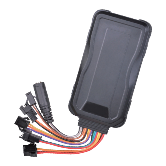
1.3 Specifications Frequency GSM 850/900/1800/1900MHz GPRS Class 12, TCP/IP Operating Voltage 9-36VDC<300mA Cold Start: <35s Location Time Hot Start:<2s Location Accuracy <10 meters Operating Temperature -20℃ ~ +70℃ Dimension 98.5(L) x 53.5(W) x 16(H) mm Weight 2.My device 2.1 Appearance Power Oil/electricity Data... -
Page 4: Led Indicators
2.2 LED indicators GPS LED indicator GSM LED indicator Power status GPS LED Indicator - Blue 0.1s ON & 0.1s OFF Searching GPS signal Steady on GPS is fixed No GPS fixed or initializing GSM LED Indicator - Green 0.1s ON & 0.1s OFF GSM initializing 0.1s ON &... -
Page 5: Installation
3. Installation 3.1 Install the SIM card Notice SIM should be inserted correctly. SIM card should have GPRS service. Open waterproof rubber plug Power on/off SIM card slot Insert SIM card SIM card's metal face up... - Page 6 3.2 Device Wire Definition Picture 1 Table 1 Line Color Description Definition 12V/24V car battery positive Black 12V/24V car battery negative Orange ACC ignition Yellow RELAY Relay 5V-OUT External power supply Blue Data receiving / backup interface Green Data sending/ backup interface GND(negative) Black Purple...
- Page 7 3.3 Device Wiring Way Analog signal Diagram 1 Power Oil/electricity Storage battery Negative trigger connection car type Door negative Relay trigger connection Data Door switch Ignition key Door light Positive trigger Oil pump Extension connection car type Door positive interface trigger connection Door switch Door light...
- Page 8 Wiring Instruction 1.The standard power supply ranges from 9V to 36VDC. Please use the power cord manufactured by the original factory. Red line means positive side while black line means negative side. During installation, negative side should connect to the ground, do not connect with other ground wires at the same time.
-
Page 9: Device Installation
3.4 Device Installation Under rear windshield Device Under front windshield Device Device Around dashboard Note: The device should face up to the sky. Metal thermal barrier or heating layer of the windshield affects the signal. Please change installation places to receive better signal. 4. -
Page 10: Main Functions
5. Main Functions 5.1 SOS In emergent case, press SOS for 3 seconds to activate SOS alarm. Then the device will send SOS SMS to preset SOS numbers and then dial the numbers in a loop for 3 times until the call is picked up. Alarm message will also send to platform. -
Page 11: Two-Way Talk
5.6 Two-way talk To activate this function, ensure that both MIC and speaker are connected well. Use pre-set SOS number to dial the device, after 10 seconds, device enters into two-way talk mode. 5.7 Displacement alarm(default OFF) Device will send movement alarm when vehicle moves out the pre- set distance (when ACC is off and GPS is fixed). -
Page 12: Restart Device
5.10 Restart device If GPRS is abnormal (device is offline), user can send SMS command RESET# to restart the device. Device will reboot after 20 seconds after receive the command. (See command list 7-16) 5.11 Door detection The device is able to detect door status. It uploads car status to platform and APP timely. -
Page 13: Platform Operation
6.Platform Operation Get registered on the designated service platform by authorized dealer, then you can start the tracking service and settings. 6.1 APN & Ser ver setting To ensure normal network operation, please confirm your APN and server setting before login. In most countries, APN could automatically adapted to local mobile operators. -
Page 14: Common Command List
7.Common Command List Edit SMS command in the right column to the device SIM number to achieve respective function as below: 1 Device status STATUS# 2 Device coordinate WHERE# 3 Location URL URL# 4 Check version VERSION# 5 Network setting GPRSSET# APN, [apnname]# APN setting... - Page 15 DISTANCE,D# GPS data upload D=0、50~10000 meter; distance interval Distance interval;default value:300, unit:meter; DEFENSE,A# Delayed defense A:1~60 minutes,set delayed defense, setting default value:10 minutes Vibration alarm SENALM,ON# (default OFF) SENALM,OFF# MOVING,ON,R,# R=100~1000; Displacement radius, Displacement alarm unit: meter setting E.g. MOVING,ON,200,# (default OFF) MOVING,OFF# Set center number :...
-
Page 16: Troubleshooting
8.Trouble shooting If you are having trouble with your device, try these troubleshooting procedures before contacting a service professional. Problems Causes Solutions The signal waves unable to transmit when use the GPS Using the GPS tracker in the tracker in the places Poor signal places that have good signal that have poor signal... -
Page 17: Warranty Instructions And Ser Vice
Warranty instructions and ser vice 1. The warranty is valid only when the warranty card is properly completed, and upon presentation of the proof of purchase consisting of original invoice indicating the date of purchase, model and serial No.of the product. We reserve the right to refuse warranty if this information has been removed or changed after the original purchase of the product from the dealer.
Need help?
Do you have a question about the GT06F and is the answer not in the manual?
Questions and answers