
Subscribe to Our Youtube Channel
Related Manuals for CYP PU-O4H4C


Summary of Contents for CYP PU-O4H4C
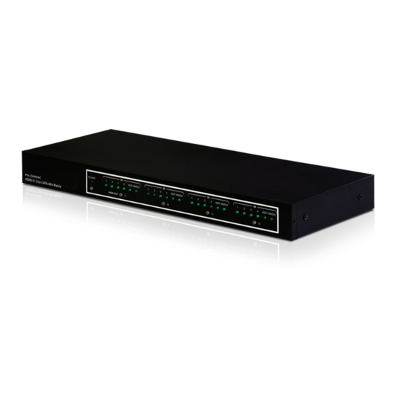
- Page 1 PU-O4H4C v1.3 HDMI 4x4 Matrix with built in HDMI over CAT6 outputs OPERATION MANUAL...
-
Page 2: Table Of Contents
Table of Contents Introduction Features Package Contents Operation Controls and Functions Front Panel Diagram Rear Panel Diagram Remote Control Pin Definitions Commands 3.5mm Connector Pin Definitions IR IN Pin Definitions IR OUT Pin Definitions RJ-45 Pin Definitions Connection Diagram Specifications... -
Page 3: Introduction
HDMI signals via CAT cabling up to 40m. The PU-O products within the PUMA range combine HDMI over CAT5e/6 (PUMA) & HDMI Matrix switcher (ORBIT) to provide versitility to HDMI installations. The PU-O4H4C HDMI matrix has 4 HDMI input and 4 CAT transmitter outputs, designed to be used with PU-1106RX receiver units. -
Page 4: Operation Controls And Functions
POWER HDCP HDMI/DVI HDCP HDMI/DVI HDCP HDMI/DVI HDCP HDMI/DVI PU-O4H4C HDMI OUT HDMI V1.3 to CAT6 4X4 Matrix 1. Remote control sensor. 2. Power switch & LED Indicator: This LED will illuminate when the power is turned 3. Input Select/Indicators (A/B/C/D): Press each “HDMI out” button repeatedly to switch to your desired source. -
Page 5: Rear Panel Diagram
4.2 Rear Panel IR OUT RS-232 CAT6 OUTPUT DC 5V IR MAIN EDID VIDEO VIDEO VIDEO VIDEO HDMI INPUT 1. EDID Control Switcher: Default factory setting is on TV, leave as it is when the display is displaying properly. Switch to STD to use built-in EDID. Note: 1. -
Page 6: Remote Control
4. IR OUT: These slots are where you connect with IR blaster cables included in the package. Place it near each designate source equipment for infrared signal sending. 5. HDMI inputs: These slots are where you connect input ports to the HDMI or DVI output of your source equipments such as DVD player or set-topbox with HDMI cables. -
Page 7: Pin Definitions
2. Input Select for HDMI OUT A: Press 1, 2, 3 or 4 to select the desired input source for HDMI OUT A. 3. Input Select for HDMI OUT B: Press 1, 2, 3 or 4 to select the desired input source for HDMI OUT B. -
Page 8: Commands
Parity: None Stop Bit: 1 bit Flow Control: None 5.1 Commands COMMAND ACTION POWER 00 Power Off (standby) POWER 01 Power On PORT 11 Output A select Input1 PORT 12 Output A select Input2 PORT 13 Output A select Input3 PORT 14 Output A select Input4 PORT 21... -
Page 9: Ir In Pin Definitions
6. 3.5mm Connectors Pin Definitions 6.1 IR IN Pin Definitions Assignment Power 5V IR Signal 6.2 IR OUT Pin Definitions Assignment IR Blaster Signal Power 5V IR Blaster Signal 6.3 RJ-45 Pin Definitions Video TX2+ DDC Bus Clock TX2- TX1+ DDC Bus Data TX0+ Power 5V... -
Page 10: Connection Diagram
7. Connection Diagram 8. Specifications 2.25Gbps (single link) Frequency Bandwidth EDID Standard, TV/Moving Port 1 Human body model: ± 10kV (air-gap di ESD Protection charge) ± 6kV (contact discharge) PCM2, PCM5.1, PCM7.1, Dolby5.1, DTS5.1, HDMI Audio Output DD+, D-TrueHD, and DTS-HD HDMI Cable In 1080p 8-bit (15M), 1080p 12-bit (15M) HDMI Cable Out... - Page 11 480i~1080p 50/60, 1080p 24, VGA~UXGA DVI Resolution 4 x HDMI female ports. Input Port 1 x IR Jack 8 x CAT5e/6 (2 for each output) Output Port 1 x IR Jack, 1 x RS-232 5V/6A, DC (US/EU standards, CE/FCC/UL Power Supply certified) Dimensions (mm) 60(W) x 50(D) x 25(H)
- Page 12 www.cypeurope.com...
Need help?
Do you have a question about the PU-O4H4C and is the answer not in the manual?
Questions and answers