Toa BS-1030 User Manual
Toa bs-1030: user guide
Hide thumbs
Also See for BS-1030:
- Brochure (46 pages) ,
- Specifications (4 pages) ,
- Instruction manual (4 pages)
Table of Contents
Advertisement
Advertisement
Table of Contents

Related Manuals for Toa BS-1030


Summary of Contents for Toa BS-1030
- Page 1 1.3k...
- Page 3 TOA Electronics Speaker Guide...
-
Page 5: Table Of Contents
Chapter 2: System Applications Paging ...12 Speech Reinforcement ...12 Background Music ...13 Foreground Music ...13 Voice/Music Combinations ...13 Presentation Audio...13 Chapter 3: Speaker Types Ceiling Speakers ...14 Wall-mount Speakers...14 In-wall Speakers...15 Paging Horns...15 Subwoofers ...16 Chapter 4: Audio Basics The Decibel ...17 Sound Pressure Level...17... - Page 6 Chapter 5: Using Speaker Specifications Determining Maximum Output: Sensitivity and Power Handling ...21 Coverage Angle ...23 Frequency Response ...23 Chapter 6: Layout and Spacing for Distributed Speaker Systems Ceiling Speakers ...24 Speaker Coverage Area ...24 Coverage Area and Ceiling Height ...25 Coverage Density vs.
- Page 7 PC-671R/RV ...38 H-1 ...39 H-2/WP ...41 Wall-mount Speakers...42 BS-1030B/W...42 BS-20W/WHT ...43 CS-64, CS-154, CS-304...44 F-160G/W, F-240G/W...47 F-505G/W, F-605G/W...49 H-3/WP ...51 Paging Horns...52 SC-610/T, SC-615/T, SC-630/T, SC-650...52 Appendix A:Wire Size Charts Appendix B: Speaker Mounting Hardware and Accessory Reference ...34 ... A-1...
-
Page 8: List Of Figures
Level change with power ...22 Ceiling speaker coverage area ...25 Speaker coverage with no overlap: hexagonal (left), square (right)...26 Speaker coverage with minimum overlap: hexagonal (left), square (right) ...26 Speaker coverage with edge-to-center overlap: hexagonal (left), square (right)...27 Wall-mount speaker coverage area...28... - Page 9 For over 75 years, we have also been an innovator in the design of high-performance speaker systems for a wide range of applications. TOA has been at the forefront in the development of specialized loudspeaker technologies for public spaces. TOA produced some of the first pro- fessional speaker systems that utilized dedicated electronic processing to optimize the speak- er’s performance.
-
Page 10: Chapter 1: Getting Started: System Design Steps
Since the best speakers for one job may be amongst the worst for another job, proper matching of the speaker to the installation is important. See Chapter 3: Speaker Types for a discussion of the types of speakers most commonly used in distributed speaker systems, and the application... - Page 11 An amplifier with inadequate power can render a sound system unintelligible at normal operating levels. Matching the amp(s) to the speaker(s)—and selecting the proper connecting cable— are important ingredients of speaker system design. See Chapter 7: Amplifier Selection and Appendix A: Wire Size Charts for this critical information.
-
Page 12: Chapter 2: System Applications
3 dB. • If more than four microphones are used, consider employing an automatic mixer, such as the TOA AX-1000A, to help maximize system gain. • The gain, or relative volume, that can be achieved depends on the relative positions of the microphones, the loudspeakers, and the listeners, in combination with the acoustical characteristics of the mics, loudspeakers, and room. -
Page 13: Background Music
In a distributed speaker design, this means using good quality speakers and relatively close spacing. -
Page 14: Chapter 3: Speaker Types
They are also applicable if the ceiling is very high or is otherwise not suitable for mounting speakers. Speakers may be mounted directly to the wall’s surface (i.e., TOA’s H series), or with a swivel bracket (F- and BS- series). -
Page 15: In-Wall Speakers
Installing the speaker inside a wall is unobtrusive and deters theft. However, installation can be costly and proper aiming and positioning are often problematic. The TOA H-1 in-wall speaker overcomes this obstacle by using rotating speaker elements to aim sound where it is needed. -
Page 16: Subwoofers
TOA Electronics Speaker Guide Subwoofers Figure 3-5 FB-100 subwoofer (left) and HB-1 in-wall subwoofer Distributed music systems are often faced with the challenges of delivering clear, high-fidelity sound with enough power to overcome high ambient noise levels at an affordable price. Meet- ing these requirements has typically involved giving up good bass response because small speakers cannot reproduce low frequencies at high levels. -
Page 17: Chapter 4: Audio Basics
(see Sound System Engineering by Don and Carolyn Davis for an in-depth discussion on the use of the decibel in sound system design). The following rules of thumb will help properly utilize the decibel in speaker system design: •... -
Page 18: Sensitivity Ratings And The Decibel
For example: If a speaker’s sensitivity is rated at 96 dB SPL with a 1 W input measured at 1 m from the speaker, then doubling the power to 2 W raises the output 3 dB to 99 dB SPL at 1 m. Doubling the power again to 4 W produces 102 dB SPL. -
Page 19: Masking, Upward Masking, And The Haas Effect
Late reflections, or late-arriving sounds from distant speakers, can be especially troublesome and can ruin both music quality and intelligibility. Good speaker layout avoids echoes from dis- tant speakers. It is also important to properly place and aim speakers to avoid echoes from dis- tant walls or other surfaces. -
Page 20: Equalization
Security covers or dedicated preset equalizers can prevent these problems. TOA offers a range of equalizer modules for our 900 series amplifiers that are optimized for specific H and F Series speakers. These cost-effective modules are preset and therefore tamper- proof. -
Page 21: Chapter 5: Using Speaker Specifications
15–25 dB higher than the background noise in its area. If the noise level is less than 45 dB SPL, the speaker should be able to produce a long-term average level of 70 dB SPL in the listening area, with undistorted peaks 10–20 dB higher. As noted on page 18, a speaker’s rated sensitivity is the on-axis loudness (dB SPL) measured at a specific distance... -
Page 22: Level Change With Distance
TOA Electronics Speaker Guide Question: What is the maximum long-term average output capability of the speaker at 80 ft? The rated long-term average power handling is 30 W. Use the chart for level change with power input (Figure 5-2) to find that our maximum output with 30 W at the reference distance of 1 m is approximately 127 dB SPL (112 + 15 dB). -
Page 23: Coverage Angle
TOA Electronics Speaker Guide Coverage Angle The coverage angle of a speaker is the angle within which the SPL is no more than 6 dB below the normalized on-axis level for a given bandwidth or frequency center. The desired coverage angle for a speaker depends on its role in the system, the number and spacing of speakers, and the acoustical environment. -
Page 24: Chapter 6: Layout And Spacing For Distributed Speaker Systems
The wider the coverage angle, the larger the coverage area, the fewer speakers needed for the same evenness of coverage. Coverage areas for all of TOA’s ceiling-mount speaker models are listed beginning on page 36 in Chapter 8: Speaker Application Tables. -
Page 25: Coverage Area And Ceiling Height
TOA’s F Series wide dispersion ceiling speakers include features engineered to avoid this common problem, resulting in higher sound quality throughout the listening area. -
Page 26: Layout Patterns
Standard spacing distances for all of TOA’s ceiling speaker models are listed in Chapter 8: Speaker Application Tables. No Overlap (spacing distance = 2r, where r is the radius of the speaker’s coverage area): The coverage area of each speaker meets but does not overlap the coverage of adjacent speakers (Figure 6-2). -
Page 27: Speaker Coverage With Edge-To-Center Overlap: Hexagonal (Left), Square (Right)
Edge-to-Center (also called center-to-center; spacing distance = radius of the coverage area): The edge of each speaker’s coverage area meets the center of adjacent speakers’ coverage areas (Figure 6-4). This is the highest speaker density commonly used in distributed systems and gives the best performance. -
Page 28: Wall-Mount Speakers
Thus, the effective vertical coverage is greater than the rated vertical coverage angle. Coverage areas for all of TOA’s wall-mount speaker models are listed in Chapter 8: Speaker Application Tables. -
Page 29: Speaker Spacing And Layout Pattern
This is because the width of the triangular coverage area is proportional to its depth. Recommended spacings for all of TOA’s wall-mount speaker models are listed in Chapter 8: Speaker Application Tables. -
Page 30: Chapter 7: Amplifier Selection
Constant voltage speaker lines (i.e., 70.7 or 25 V) do not actually have constant voltage on them. Their line impedance is varied using transformers to achieve the same theoretical maximum voltage in any system. -
Page 31: Subwoofer Power Requirements
High-Quality Paging System A workspace needs reliable and intelligible paging in all areas, for both standing and seated listeners. The room is 30 x 40 ft with a 10 ft ceiling. TOA model F-121CM speakers are selected for their wide dispersion. -
Page 32: Outdoor Paging System
Paging is needed in an outdoor area. The area is 100 x 200 ft (20,000 sq. ft), and the speakers will be mounted on poles along the center of the area (200 ft). TOA model SC-615T is selected for its high efficiency and wide area coverage. -
Page 33: High-Quality Multi-Purpose System
A multi-purpose room needs high-quality sound for video and A/V presentations, speech rein- forcement, and background music for company functions. The room is 40 x 80 ft with a 12 ft ceiling. TOA model F-121CM speakers are selected for their ability to meet the wide-ranging requirements. -
Page 34: Chapter 8: Speaker Application Tables
All Speakers Speaker height is relative to listener height. If the value for Height Above Listener is 2, that means the speakers are placed 2 ft above the expected ear level of the listeners. -
Page 35: Wall-Mount Speakers
Coverage Depth refers to the minimum, or perpendicular, distance between the far limit of the coverage area and the wall or surface that the speaker is mounted on. For best coverage, listen- ers should be no farther from the wall (pole, etc.) than this. -
Page 36: Ceiling-Mount Speakers
TOA Electronics Speaker Guide Ceiling-mount Speakers F-101C/M Height Above Coverage Listener Area (sq. ft) Edge to Center h-l (ft) Overlap 1018 1257 F-101C/M Specifications Coverage Angle Frequency Response Sensitivity (1 W / 1 m) Power Handling Transformer Taps (F-101CM only) -
Page 37: F-121C/M
TOA Electronics Speaker Guide F-121C/M Height Coverage Above Area (sq. Listener Edge to Center h-l (ft) Overlap 1357 1847 2413 3054 3770 F-121C/M Specifications Coverage Angle Frequency Response Sensitivity (1 W / 1 m) Power Handling Transformer Tap (F-121CM only) -
Page 38: Pc-671R/Rv
TOA Electronics Speaker Guide PC-671R/RV Height Above Coverage Listener Area (sq. ft) Edge to Center h-l (ft) Overlap PC-671R/RV Specifications Coverage Angle Frequency Response Sensitivity (1 W / 1 m) Power Handling Transformer Taps Components PC-671R/RV Coverage And Spacing Spacing (ft) Min. - Page 39 TOA Electronics Speaker Guide H-1 Coverage And Spacing (Ceiling Mount) Height Above Coverage Listener Area (sq. ft) Edge to Center h-l (ft) Overlap H-1 Specifications Coverage Angle 120º H x 100º V Frequency Response 120 Hz – 20 kHz Sensitivity (1 W / 1 m)
- Page 40 TOA Electronics Speaker Guide Height Above Downward Coverage Listener Tilt h-l (ft) (degrees) H-1 Coverage and Spacing (Wall Mount) Maximum Spacing for Coverage Area Rated Coverage Depth Depth (ft) (sq. ft) Speaker Application Tables Max. SPL for Farthest On-Axis (ft)
-
Page 41: H-2/Wp
TOA Electronics Speaker Guide H-2/WP Coverage h-l (ft) Area (sq. ft) Edge to Center Overlap H-2/WP Specifications Coverage Angle Frequency Response Sensitivity (1 W / 1 m) Power Handling Transformer Taps Components Weather-Resistant version 900 Series Equalizer Module H-2/WP Coverage And Spacing Spacing (ft) Min. -
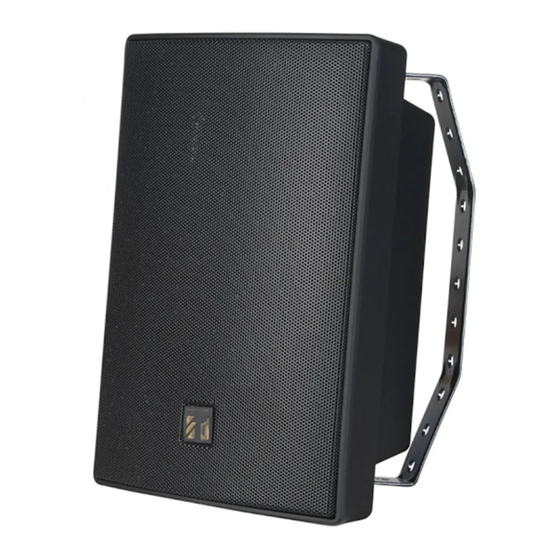
Page 42: Wall-Mount Speakers
TOA Electronics Speaker Guide Wall-mount Speakers BS-1030B/W Height Above Downward Coverage Listener h-l Tilt (ft) (degrees) BS-1030B/W Specifications Coverage Angle Frequency Response Sensitivity (1 W / 1 m) 90 dB Power Handling Transformer Taps Components Installation Accessories BS-1030B/W Coverage and Spacing... -
Page 43: Bs-20W/Wht
TOA Electronics Speaker Guide BS-20W/WHT Height Downward Coverage Above Tilt Listener h-l (degrees) (ft) BS-20W/WHT Specifications Coverage Angle Frequency Response Sensitivity (1 W / 1 m) 94 dB Power Handling Transformer Taps Components Installation Accessories BS-20W/WHT Coverage and Spacing Coverage... -
Page 44: Cs-64, Cs-154, Cs-304
TOA Electronics Speaker Guide CS-64, CS-154, CS-304 Coverage Angle (2 kHz) 100º H x 100º V Frequency Response 130 Hz – 13 kHz Sensitivity (1 W / 1 m) 96 dB Power Handling (transformer) 70.7 V: 0.5, 1.5, 3, 6 W... - Page 45 TOA Electronics Speaker Guide Height Above Downward Listener h-l Tilt (ft) (degrees) Height Above Downward Listener h-l Tilt (ft) (degrees) CS-64 Coverage and Spacing Coverage Coverage Maximum Spacing Area Depth for Rated Coverage (sq. ft) (ft) CS-154 Coverage and Spacing...
- Page 46 TOA Electronics Speaker Guide Height Above Downward Listener h-l Tilt (ft) (degrees) CS-304 Coverage and Spacing Coverage Coverage Maximum Spacing Area Depth for Rated Coverage (sq. ft) (ft) 1537 2402 1097 1433 1189 Speaker Application Tables Max. SPL for Farthest On-Axis...
-
Page 47: F-160G/W, F-240G/W
TOA Electronics Speaker Guide F-160G/W, F-240G/W Coverage Angle Frequency Response Sensitivity (1 W / 1 m) Power Handling Transformer Taps (F-160GM/WM, F-240GM/WM only) Components Installation Accessories F-160/F-240 Specifications F-160 90º H x 90º V 90º H x 90º V 100 Hz – 20 kHz 65 Hz –... - Page 48 TOA Electronics Speaker Guide Height Above Downward Listener h-l Tilt (ft) (degrees) F-160/F-240 Coverage and Spacing Coverage Coverage Maximum Spacing Area Depth for Rated Coverage (sq. ft) (ft) Speaker Application Tables Max. SPL for Farthest On-Axis Listener (dB) Depth (ft)
-
Page 49: F-505G/W, F-605G/W
TOA Electronics Speaker Guide F-505G/W, F-605G/W Coverage Angle Frequency Response Sensitivity (1 W / 1 m) Power Handling Impedance Components Installation Accessories F-505/F-605 Specifications F-505G/W 60º H x 40º V 70 Hz – 20 kHz 93 dB 80 W pink noise LF: 8"... - Page 50 TOA Electronics Speaker Guide Height Above Downward Listener h-l Tilt (ft) (degrees) F-505/F-605 Coverage and Spacing Coverage Coverage Maximum Spacing Area Depth for Rated Coverage (sq. ft) (ft) 1071 1674 2410 1008 1276 1575 1005 Speaker Application Tables Max. SPL for...
-
Page 51: H-3/Wp
TOA Electronics Speaker Guide H-3/WP Height Above Downward Listener h-l Tilt (ft) (degrees) H-3/WP Specifications Coverage Angle Frequency Response Sensitivity (1 W / 1 m) Power Handling Transformer Taps Components Installation Accessories 900 Series Equalizer Module H-3/WP Coverage and Spacing... -
Page 52: Paging Horns
TOA Electronics Speaker Guide Paging Horns SC-610/T, SC-615/T, SC-630/T, SC-650 SC610/T Coverage 70º H x 100º V Angle Frequency 315 Hz – 12.5 kHz Response Sensitivity 110 dB (1 W / 1 m) Power 10 W Handling Transformer 70.7 V: 0.5, 1.5, 3, 6 W... - Page 53 TOA Electronics Speaker Guide Height Above Downward Listener h-l Tilt (ft) (degrees) Height Above Downward Listener h-l Tilt (ft) (degrees) SC-610/T Coverage and Spacing Coverage Coverage Maximum Spacing Area Depth for Rated Coverage (sq. ft) (ft) Depth (ft) 1129 1765...
- Page 54 TOA Electronics Speaker Guide Height Above Downward Listener h-l Tilt (ft) (degrees) SC-630/T Coverage and Spacing Coverage Coverage Maximum Spacing Area Depth for Rated Coverage (sq. ft) (ft) Depth (ft) 1298 1869 2543 3322 4204 5190 6280 1183 Speaker Application Tables Max.
- Page 55 TOA Electronics Speaker Guide Height Above Downward Listener h-l Tilt (ft) (degrees) SC-650 Coverage and Spacing Coverage Coverage Maximum Spacing Area Depth for Rated Coverage (sq. ft) (ft) Depth (ft) 1173 1689 2299 3003 3800 4692 5677 Speaker Application Tables Max.
-
Page 57: Appendix A:wire Size Charts
TOA Electronics Speaker Guide Appendix A: Wire Size Charts Speaker Cable Lengths (ft) and Gauges (AWG) for 70.7 V Line with 1 dB Power Loss Table 1 Wire Gauge 70.7 V (AWG) Load Impedance Load Power 24.5 12.2 Speaker Cable Lengths (ft) and Gauges (AWG) for 25 V Line with 1 dB Power Loss... -
Page 58: Appendix B: Speaker Mounting Hardware And Accessory Reference
TOA Electronics Speaker Guide Appendix B: Speaker Mounting Hardware and Accessory Reference Model Mounting Hardware Ceiling/Wall-Mount Bracket included BS-1030B/W WCB-12/W Ceiling/Wall-Mount Bracket (optional) BS-20W/WHT Ceiling/Wall-Mount Bracket included BBF-100 Back-box (requires TBF-100) F-101C/M TBF-100 Tile-bridge BBF-100 Back-box (requires TBF-100) F-121C/M TBF-100... - Page 60 TOA E LECTRONICS TEL: 800-733-7088 FAX: 800-733-9766 TOA C ANADA ORPORATION : 905-564-3570 : 905-564-3569 © 2002, TOA Electronics, Inc. Literature Order #: L-SPKRGUIDE 1.3k...
Need help?
Do you have a question about the BS-1030 and is the answer not in the manual?
Questions and answers