Table of Contents
Advertisement
Quick Links
Tel +1 (717) 767-6511
Fax +1 (717) 764-0839
www.redlion.net
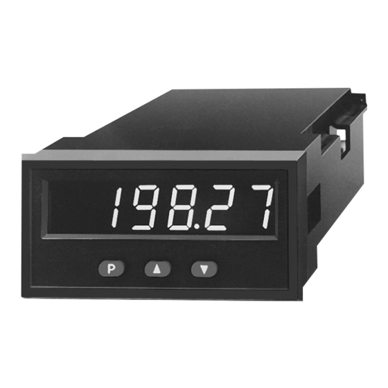
MODEL IMA - APOLLO 6-DIGIT INTELLIGENT SERIAL SLAVE DISPLAY
DISPLAYS 6 DIGITS OF SERIAL ASCII DATA
INPUT ISOLATED 20 mA LOOP
STATE-OF-THE-ART DIGITAL ELECTRONICS FOR GREATER
RELIABILITY
FULL 6-DIGIT, 7 SEGMENT, HIGH VISIBILITY, 0.56" (14.2 mm)
HIGH, RED LED DISPLAY
PROGRAMMABLE FRONT PANEL LOCK-OUT MENU
PEAK/VALLEY MEMORY FUNCTION
DUAL ALARM RELAY OUTPUTS (optional)
NEMA 4/IP65 SEALED METAL FRONT BEZEL
DIN STD BEZEL 1.89" (48 mm) x 3.78" (96 mm)
GENERAL DESCRIPTION
The Apollo Intelligent Serial Slave Display (IMA) accepts ASCII data from
either a terminal, host computer, or Red Lion Controls product with serial
communications, and displays the received data. The data may be numeric,
alphabetic and/or punctuation, the parameters of how the data is interpreted by
the IMA is covered in detail in the 20 mA current loop serial communications
section. Serial communication is accomplished via two 20 mA current loops.
The IMA provides two 20 mA current sources. The first source is dedicated to
the output loop (TBA #12) and can power up to seven units on its loop. The
second source (TBA #7) is a quasi current source (1KΩ resistor to +18 VDC)
which can power up to three units on its loop. Note: One source is required to
transmit and one source is required to receive. The peak and valley (max/min)
values can be recalled at the touch of a button. A full 6-digit, 7-segment display
accommodates virtually any process engineering unit. English-style display
prompts and front panel buttons aid the operator through set-up and operation.
A front panel lock-out menu protects set-up data from unauthorized personnel.
Programmable E1-CON can be utilized for alarm, display hold and reset
operations. All set-up data is stored in E
minimum of 10 years without power. All values are retained at power-down.
Optional dual relays with parallel solid state outputs are fully programmable
to operate in a wide variety of modes to suit many alarm applications.
The IMA has several built-in diagnostic functions to alert operators of most
any malfunction. Extensive testing of noise interference mechanisms and full
burn-in makes the IMA extremely reliable in industrial environments. The die-
cast front bezel meets NEMA 4/IP65 requirements for washdown applications
when properly installed. Plug-in style terminal blocks simplify installation and
wiring change-outs.
DIMENSIONS In inches (mm)
2
PROM, which will hold data for a
Note: Recommended minimum clearance (behind the panel) for mounting clip installation is 2.1" (53.3) H x 5.5" (140) W
SAFETY SUMMARY
All safety related regulations, local codes and instructions that appear in the
manual or on equipment must be observed to ensure personal safety and to
prevent damage to either the instrument or equipment connected to it. If
equipment is used in a manner not specified by the manufacturer, the protection
provided by the equipment may be impaired.
Do not use this unit to directly command motors, valves, or other actuators
not equipped with safeguards. To do so, can be potentially harmful to persons
or equipment in the event of a fault to the unit.
CAUTION: Read complete
instructions prior to installation
and operation of the unit.
ORDERING INFORMATION
MODEL NO.
DESCRIPTION
Intelligent Serial
IMA
Slave Display
For information on Pricing, Enclosures & Panel Mount Kits refer to the RLC
catalog or contact your local RLC distributor.
1
Bulletin No. IMA/IM-G
Drawing No. LP0201
Released 2/05
CAUTION: Risk of electric shock.
PART NUMBERS
DUAL ALARMS
115/230 VAC
NO
IMA04161
YES
IMA04164
PANEL CUT-OUT
.
Advertisement
Table of Contents

Related Manuals for red lion IMA


Summary of Contents for red lion IMA
- Page 1 IMA is covered in detail in the 20 mA current loop serial communications provided by the equipment may be impaired.
-
Page 2: Specifications
Part 1. Punctuation: “.” “,” “-” “blank” IP65 Enclosure rating (Face only), IEC 529 Note: If any characters received by the IMA are NOT in the above list, a Type 4 Enclosure rating (Face only), UL50 blank space will be substituted. -
Page 3: Installations And Connections
INSTALLATIONS & CONNECTIONS INSTALLATION ENVIRONMENT Before installing the IM into the panel, the user should first become familiar The bezel should be cleaned only with a soft cloth and neutral soap product. with the unit. It may also be desirable to program the unit for the application. Do NOT use solvents. -
Page 4: Wiring Connections
To reduce the chance of noise spikes entering the AC line and affecting the IMA, the AC power should be relatively “clean” and within the specified +/-10% variation limit. Drawing power from heavily loaded circuits or circuits which also power loads that cycle on and off, (contactors, relays, motors, machinery, etc.) should be avoided. -
Page 5: Quick Programming
PROGRAMMABLE FUNCTIONS Programming of the IMA is divided into modular steps. Each module is a short sequence of data entries. The front panel buttons “UP” and “DOWN”, (shown as “arrows” on the front panel) are used to change the data and set-ups, while the “P”... - Page 6 PROGRAMMING THE IMA Prior to installing and operating the IMA, it may be necessary to change the set- DISPLAY RESULT OF “P” BUTTON ups to have the display correspond to a particular application. Although the IMA has been programmed at the factory, the set-ups will generally have to be changed.
- Page 7 “2” - A negative going edge resets only the peak buffer and the manual override of alarms for system start-up and other IMA enters a peak reading display mode as long as the pin is unusual events such as system testing.
- Page 8 MODULE #5 - PROGRAM ALARM/SETPOINT If the alarm option is installed, this module is used to configure the operation of the alarms to a variety of combinations. The programmable options are HI/LO acting, auto/manual reset (latching), tracking, display alarms, alarm ALARM #1 HIGH OR LOW ACTING values and hysteresis (deadband) values.
-
Page 9: General Description
IMA is 1 start bit, 7 data bits, 1 odd parity bit and 1 stop bit. The baud locations. When used in this manner, the IMA can be set-up as receive only and rates are programmable and the choices are: 300, 600, 1200 and 2400. -
Page 10: Command String Examples
IMA will recognize. a command to be directed to a specific unit on the loop. If the IMA is assigned an address of “0”, transmission of the address command is not required. This is... - Page 11 IMA: Baud rate 2400, address 0. Print code and abbreviated transmission are NOT applicable. Current loop connections are made so that the IMT is in transmit mode only and the IMA is in receive mode only. A key switch is installed at program disable terminal to prevent access to certain parameters after set-up.
-
Page 12: Troubleshooting
Current loop connections and set-up parameters are done so the Gemini An IMA is used for the above requirements. 2000 is in the transmit mode only and the IMA is receive only. Alarms are Communication set-ups: programmed into the IMA to activate if the desired rate becomes too HI or Gemini 2000: Baud rate 2400 (switches 1 &...
Need help?
Do you have a question about the IMA and is the answer not in the manual?
Questions and answers