Table of Contents
Advertisement
Advertisement
Table of Contents

Subscribe to Our Youtube Channel
Related Manuals for pronovost P-INV-74


Summary of Contents for pronovost P-INV-74
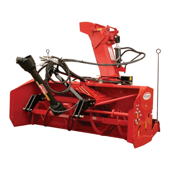
- Page 1 OPERATOR'S / PARTS MANUAL Snowblowers Models P-INV-74 No. C3002 05/2010...
- Page 2 Copyright © Les Machineries Pronovost Inc., 2010 All rights reserved. Printed in Canada.
-
Page 3: Table Of Contents
Maintenance ......................14 Storage ........................15 Trouble Shooting ......................16 Specifications ......................18 Parts List ........................19 Snowblowers P-INV-74 .................. 19 Semi-industrial Chute PSIG-INV-GR1 ............. 22 Options ......................23 P.T.O. Shaft 8114-EG ..................24 Gear Box 8251 ....................25 Cylinder 25TR04 ....................26 Hydraulic Motor MLH100, MLH125 &... -
Page 5: Introduction
INTRODUCTION CONGRATULATIONS! Thank you for choosing PRONOVOST. We are NOW take a moment to enter the model, serial confident this equipment will meet your requirements number and the date of purchase of your Snowblower in terms of quality, performance and reliability. -
Page 6: Safety
SAFETY GENERAL SAFETY WHEN YOU SEE THIS SYMBOL Prolonged exposure to noise may hamper hearing. Protect yourself by wearing adequate protection devices. 9) Hydraulic fluids under pressure can damage your skin. Do not use your hands to locate a leak. 10) Before the beginning of the snow season, inspect all areas where the Snowblower will be used and remove any object which may cause an accident and/or damage... -
Page 7: Safety With Maintenance
SAFETY (cont'd) Stop engine and relieve all hydraulic pressures before Before unplugging the chute, always disengage the doing inspection, maintenance or repairs. P.T.O., stop the engine and relieve all hydraulic pressu- res. 3) Never perform any work under the Snowblower while it is supported only by the tractor's hydraulic system. -
Page 8: Decals
DECALS SAFETY DECALS The safety decals are affixed wherever special safety precautions are indicated. Locate them on the machine and read them carefully. If a decal is damaged, lost or illegible, install a new one. The following photos indicate where each one must be installed. Figure 4 Decal B Part no.: 190-07722... - Page 9 DECALS (cont'd) Figure 9 Figure 7 Decal D Part no.: 190-06651 Figure 10 Decal F Part no.: 190-11581 Figure 8 Decal E Pièce no.: 190-07611 Figure 11 Decal G Part no.: 190-11641 - 9 -...
- Page 10 DECALS (cont'd) Figure 12 Decal H Part no.: 190-10991 Figure 13 Figure 14 Part no.: A108 - 10 -...
-
Page 11: Maintenance Decals
DECALS (cont'd) MAINTENANCE DECALS The maintenance decals indicate the points requiring lubrication. Refer to maintenance section for more details. Figure 16 Part no.: A 106 Figure 15 Part no.: A 109 - 11 -... -
Page 12: Assembly
ASSEMBLY ASSEMBLY 1) The Snowblower is shipped partly assembled. 2) Install 3-point system according to the model of your Snowblower. (See section 10 for parts numbers). Use the holes most convenient to the type of tractor used (Fig. 17). 3) Install P.T.O. shaft with the shear pin end onto the Snowblower gear box. -
Page 13: Start-Up
STARTING-UP START-UP PROCEDURES 1) Check oil level in gearbox. Adjust to required oil level as per drawing in Parts List section. Use SAE 80W90 oil. 2) Lubricate all points with a good quality multipurpose grease. 3) Check chain take-up adjustment. The spring maintaining the tension must be compressed to a length between 3"... -
Page 14: Maintenance
MAINTENANCE 1) Wipe off all grease fittings with a clean cloth 7) Check tension of drive chain every 24 hours of before adding grease in order to avoid injecting operation and adjust if necessary. dirt and sand. 8) Check for tightness of bearing collars every 48 2) Repair or replace damaged grease fittings. -
Page 15: Storage
STORAGE 1) Store the Snowblower in a cool, dry place. 5) Thoroughly inspect all parts of the Snowblower. Replace or repair worn or defective parts. 2) Support the Snowblower with wooden blocks. 6) Touch-up or repaint if necessary. 3) Keep all piston rods in the retracted position. This will assure better protection against the elements. -
Page 16: Troubleshooting
TROUBLESHOOTING P.T.O. SHAFT PROBLEM POSSIBLE CAUSE CORRECTION - Premature wear of U-joints and/ - Insufficient lubrication. - Follow lubrication or bluish color of cross journals. recommendations. - Replace defective U-joints. - Excessive working angle. - Make sure the Snowblower inlet face is perpendicular to the ground and if possible readjust 3-point hitch in order to position... - Page 17 TROUBLESHOOTING (cont'd) SNOWBLOWER PROBLEM POSSIBLE CAUSE CORRECTION - Raise P.T.O. speed to a minimum - The snow is not being thrown as - Tractor RPM too low. of 540 RPM. far as usual. - Adjust impeller blades closer to - Gap too wide between impeller drum outlet (1/8"...
-
Page 18: Specifications
SPECIFICATIONS Model P-INV-74 Horse power recommended 35 to 65 HP Working width 74" Cutting height 28" Height - chute base 30" Drum diameter 26" Depth of drum 9" Impeller blades 4 blades Number of shear bolts 1 for impeller, 1 on auger drive Size of impeller shaft 1 9/16"... -
Page 19: Parts List
SNOWBLOWER P-INV-74 170-05463 - 19 -... - Page 20 SNOWBLOWER P-INV-74 (cont'd) REF. PART # DESCRIPTION 120-07642 Frame P-INV-74 ...................... 140-25432 Scraper blade 3/8" x 2 1/2" x 72 3/4" lg standard steel ..........140-25432 Scraper blade 3/8" x 2 1/2" x 72 3/4" lg standard steel (rear mount scraper blade) ..opt.
- Page 21 SNOWBLOWER P-INV-74 (cont'd) REF. PART # DESCRIPTION 110-44901 Adjustment plate for gearbox + 4 nuts 1/2" NC ............300-40280 Bolt 1/2" NC x 1 1/4" lg + lock washer ..............8114-EG P.T.O. shaft ......................8021 Sprocket 60 A38 T 1¼" ø ..................
-
Page 22: Semi-Industrial Chute Psig-Inv-Gr1
SEMI-INDUSTRIAL CHUTE PSIG-INV-GR1 170-5681 REF. PART # DESCRIPTION 110-45431 Chute base (serial number 33233 to 33916) ............ 110-45432 Chute base (serial number 33917 and up) ............110-22871 Lower chute deflector .................. 110-22861 Upper chute deflector .................. 140-14171 Connecting rod ................... 110-46011 Access panel (serial number 33233 to 33916) .......... -
Page 23: Options
OPTIONS 170-05781 REF. PART # DESCRIPTION 130-85661 Semi-industrial scraper blade, carbon steel, not reversible, not sharpened 1/2" x 3" x 72 3/4" ......319-38310 Plow bolt 7/16" NC x 1 1/2" lg + nut & lockwasher .................... 130-85651 Semi-industrial scraper blade, stainless steel, not reversible, not sharpened 1/2" x 3" x 72 3/4" ......190-13111 Scraper blade, TIVAR 1"... -
Page 24: P.t.o. Shaft # 8114-Eg
P.T.O. SHAFT # 8114-EG (T50) REF. PART # DESCRIPTION 8221 Safety shear yoke (2 bolts) ..................8073 U joint + 4 retaining rings + 1 grease fitting ............. 8061 Retaining ring ......................8110 Grease fitting ......................8079 Yoke for inner tube ....................6341 Stopper for inner tube ..................... -
Page 25: Gear Box 8251
GEAR BOX # 8251 (T27D) 170-05581 Oil volume required: 1.2 liters Use SAE 80W90 oil or equivalent. Vent plug (oil filler plug) Oil level plug Drain plug REF. PART # DESCRIPTION 8043 Casing ........................30208-A Roller bearing ......................8045 Inside circlip 80mm ....................8046 Oil seal 40 x 80 x 12mm .................. -
Page 26: Cylinder 25Tr04
CYLINDER 25TR04 170-02141 14 ¼" REF. PART # DESCRIPTION 1 See #RK25TR O-ring 1/8" x 2¼" x 2½" ................2 See #RK25TR Back-up 2½" o.d. x 3/16 ø ................. 3 See #RK25TR O-ring 3/16" x 2 1/8" x 2½" ............... 4 See #RK25TR O-ring 1/16"... -
Page 27: Hydraulic Motor Mlh100, Mlh125 & Mlh250
HYDRAULIC MOTOR MLH100, MLH125 & MLH250 CUSHION VALVE H110 MOTOR REF. PART # DESCRIPTION 8368 Set of seals ....................8369 Key for "Orbit" motor ................. - 27 -... -
Page 28: Torque Chart
TORQUE CHART TORQUE SPECIFICATION TABLE Thread UNC and UNF Grade 2 Grade 5 Grade 8* Bolt size Torque Torque Torque Pound feet Newton meters Pound feet Newton meters Pound feet Newton meters Inches min. max. min. max. min. max. min. max. -
Page 29: Warranty
Transportation charges are the responsibility of the Our obligation is limited to the replacement or repair customer. This warranty is not transferable. of the defective part. PRONOVOST accepts no res- ponsibility for direct or indirect consequential dama- Hydraulic cylinders and motors are covered by the ges of any kind. - Page 32 Ce manuel est aussi disponible en français. Veuillez téléphoner. INNOVATION - EXCELLENCE LES MACHINERIES PRONOVOST INC. 260, Haut du Lac Sud (route 159), Saint-Tite, Quebec, Canada, G0X 3H0 Tel.: (418) 365-7551, Fax: (418) 365-7954 www.pronovost.qc.ca...
Need help?
Do you have a question about the P-INV-74 and is the answer not in the manual?
Questions and answers