Table of Contents
Advertisement
Advertisement
Table of Contents

Related Manuals for pronovost PGS-740


Summary of Contents for pronovost PGS-740
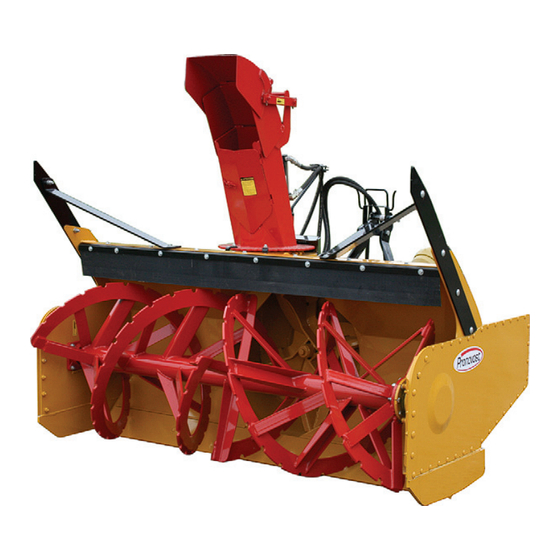
- Page 1 OPERATOR'S / PARTS MANUAL Snowblowers Model PGS-740 & PGS-800 No. C3302 11/2011...
- Page 2 Copyright © Les Machineries Pronovost Inc., 2011 All rights reserved. Printed in Canada.
-
Page 3: Table Of Contents
Storage ........................17 Trouble Shooting ...................... 18 Specifications......................20 Parts List ........................21 Snowblower PGS-740 PGS-800 ..............21 Hydraulic chute rotation kit for motor ............24 Semi-industrial Chute PSIG-5472 ..............26 P.T.O. Shaft T60 # 8202 ................. 27 Gear Box # 8251 ..................... 28 Cylinder 25TR04 .................... -
Page 5: Introduction
INTRODUCTION CONGRATULATIONS! Thank you for choosing PRONOVOST. We are NOW take a moment to enter the model, serial confident this equipment will meet your requirements number and the date of purchase of your Snowblower in terms of quality, performance and reliability. -
Page 6: Safety
SAFETY GENERAL SAFETY WHEN YOU SEE THIS SYMBOL 8) Prolonged exposure to noise may hamper hearing. Protect yourself by wearing adequate protection devices. 9) Hydraulic fluids under pressure can damage your skin. Do not use your hands to locate a leak. 10) Before the beginning of the snow season, inspect all areas where the Snowblower will be used and remove any object which may cause an accident and/or damage... -
Page 7: Safety With Maintenance
SAFETY (cont'd) 2) Stop engine and relieve all hydraulic pressures before 10) Before unplugging the chute, always disengage the doing inspection, maintenance or repairs. P.T.O., stop the engine and relieve all hydraulic pres- sure. 3) Never perform any work under the Snowblower while it is supported only by the tractor's hydraulic system. -
Page 8: Decals
DECALS SAFETY DECALS The safety decals are affixed wherever special safety precautions are indicated. Locate them on the machine and read them carefully. If a decal is damaged, lost or illegible, install a new one. The following photos indicate where each one must be installed. Figure 3 Figure 4 Decal B... - Page 9 DECALS (cont'd) Figure 6 Figure 7 Decal C Part no.: 190-11641 Decal E in Fig. 8 is located directly on the P.T.O. shaft. It is not visible when the safety shield is in place. It must never be visible when you operate the equipment.
- Page 10 DECALS (cont'd) Figure 12 Figure 9 Decal F Part no.: A 109 Figure 13 Decal G Part no.: 190-10991 Figure 10 Figure 11 Decal D Part no.: A103 Figure 14 - 10 -...
- Page 11 DECALS (cont'd) Figure 17 Decal J Part no.: 190-07611 Figure 15 Decal H Part no.: 190-06651 Figure 18 Figure 16 - 11 -...
-
Page 12: Maintenance Decals
DECALS (cont'd) MAINTENANCE DECALS The maintenance decals indicate the points requiring lubrication. Refer to maintenance section for more details. A 105 A 106 Figure 19 Figure 21 Figure 22 Figure 20 Decal L Part no.: 190-11581 - 12 -... -
Page 13: Assembly
ASSEMBLY ASSEMBLY 1) The Snowblower is shipped partly assembled. 2) Install 3-point system according to the model of your Snowblower. (See section 10 for part numbers). Use the holes most convenient to the type of tractor used (Fig. 23). 3) Install P.T.O. shaft with the shear pin end onto the Snowblower gear box. -
Page 14: Hydraulic Chute Kit: Motor
ASSEMBLY (cont'd) HYDRAULIC CHUTE ROTATION Motor 1) Install U-shaped UHMW piece , place chute on Snowblower and secure with retaining bracket and bolts provided. 2) Install the mounting plate; put the required spacers between mounting plate and base of chute (see p. 24 &... -
Page 15: Start-Up
STARTING-UP START-UP PROCEDURES 1) Check oil level in gearbox and in speed reducer if so equipped. Use SAE 80W90 gear box oil. 2) Check oil level in auger drive chain box. Fill to Use SAE 80W90 oil (Fig. 28). level plug. Oil level ... -
Page 16: Maintenance
MAINTENANCE GENERAL MAINTENANCE 1) Wipe off all grease fittings with a clean cloth 7) Check tension of drive chain every 24 hours of before adding grease in order to avoid injecting operation and adjust if necessary. dirt and sand. 8) Check for tightness of bearing collars every 48 2) Repair or replace damaged grease fittings. -
Page 17: Storage
STORAGE 1) Store the Snowblower in a cool, dry place. 5) Thoroughly inspect all parts of the Snowblower. Replace or repair worn or defective parts. 2) Support the Snowblower with wooden blocks. 6) Touch-up or repaint if necessary. 3) Keep all piston rods in the retracted position. This will assure better protection against the elements. -
Page 18: Troubleshooting
TROUBLESHOOTING P.T.O. SHAFT PROBLEM POSSIBLE CAUSE CORRECTION - Premature wear of U-joints and/ - Insufficient lubrication. - Follow lubrication or bluish color of cross journals. recommendations. - Replace defective U-joints. - Excessive working angle. - Make sure the Snowblower inlet face is perpendicular to the ground and if possible readjust 3-point hitch in order to position... - Page 19 TROUBLESHOOTING (cont'd) SNOWBLOWER PROBLEM POSSIBLE CAUSE CORRECTION - Raise P.T.O. speed to a minimum - The snow is not being thrown as - Tractor RPM too low. of 540 RPM. far as usual. - Adjust impeller blades closer to - Gap too wide between impeller drum outlet (1/8"...
-
Page 20: Specifications
SPECIFICATIONS Model PGS-740 PGS-800 Horse power required 35 to 65 HP Approximate performance 500 tons imp./hour (tractor 60 HP) Height - chute base 35" Chute rotation On anti-friction ring, for hydraulic motor Frame height 36 3/4" Lateral cutting height 58 1/2"... -
Page 21: Parts List
SNOWBLOWER PGS-740 PGS-800 170-05873 - 21 -... - Page 22 SNOWBLOWER PGS-740 PGS-800 (cont'd) REF. PART # DESCRIPTION 140-26831 Back plate for the shroud ................. 140-26971 Back plate for the shroud ................. 300-34280 Bolt 5/16" NC x 1 1/4" lg + nylon locknut ..........190-13861 Shroud ....................190-13891 Shroud ....................
- Page 23 PART # DESCRIPTION 140-26321 Key 1/2" x 1/2" x 2 3/8" ................110-47111 Auger drive shaft for PGS-740 ............... 110-49091 Auger drive shaft for PGS-800 ............... 160-27622 Aluminium-bronze bushing 1 1/2" i.d. x 1 3/4" o.d. x 2" lg ......
-
Page 24: Hydraulic Chute Rotation Kit For Motor
HYDRAULIC CHUTE ROTATION KIT SP-7480-PGS 170-06271 - 24 -... - Page 25 HYDRAULIC CHUTE ROTATION KIT SP-7480-PGS (cont'd) REF. PART # DESCRIPTION 300-32220 Bolt 1/4" NC x 3/4" lg + lock washer ............110-44331 Sprocket 9 teeth ..................323-36160 Hexagonal socket setscrew 3/8" NC x 3/8" lg ..........300-38280 Bolt 7/16" NC x 1 1/4" lg + nylon locknut ........... 300-36250 Bolt 3/8"...
-
Page 26: Semi-Industrial Chute Psig-5472
SEMI-INDUSTRIAL CHUTE PSIG-5472 170-03513 REF. PART # DESCRIPTION 110-22861 Upper chute deflector ................. 110-22871 Lower chute deflector ................110-36763 Chute base ....................140-14171 Connecting rod ..................150-05391 Spacer for connecting rod ................Std. Grease fitting 1/4" - 28 droit ............... 378-36500 washer ..................... -
Page 27: Shaft T60 # 8202
P.T.O. SHAFT # 8202 (T60) REF. PART # DESCRIPTION 8237 Safety shear yoke (2 bolts) ..................8238 U joint + 4 retaining rings + 1 grease fitting ............. 8061 Retaining ring ......................8110 Grease fitting ......................8239 Yoke for inner tube ....................8075 Stopper for inner tube ..................... -
Page 28: Gear Box # 8251
GEAR BOX # 8251 (T27D) 170-05581 Oil volume required: 1.2 liters Use SAE 80W90 oil or equivalent. Vent plug (oil filler plug) Oil level plug Drain plug REF. PART # DESCRIPTION 8043 Casing ........................30208-A Roller bearing ......................8045 Inside circlip 80mm ....................8046 Oil seal 40 x 80 x 12mm .................. -
Page 29: Cylinder 25Tr04
CYLINDER 25TR04 170-02141 14 ¼" REF. PART # DESCRIPTION 1 See #RK25TR O-ring 1/8" x 2¼" x 2½" ................2 See #RK25TR Back-up 2½" o.d. x 3/16 ø ................. 3 See #RK25TR O-ring 3/16" x 2 1/8" x 2½" ............... 4 See #RK25TR O-ring 1/16"... -
Page 30: Hydraulic Motor Mlh250
HYDRAULIC MOTOR MLH250 CUSHION VALVE H110 MOTOR REF. PART # DESCRIPTION 8368 Set of seals ....................8369 Key for "Orbit" motor ................. - 30 -... -
Page 31: Torque Chart
TORQUE CHART TORQUE SPECIFICATION TABLE Thread UNC and UNF Grade 2 Grade 5 Grade 8* Bolt size Torque Torque Torque Pound feet Newton meters Pound feet Newton meters Pound feet Newton meters Inches min. max. min. max. min. max. min. max. -
Page 32: Warranty
WARRANTY PRONOVOST warrants this product to the initial All PRONOVOST spare parts purchased are covered purchaser for the period of one year from the date of by a three (3) month warranty. purchase against defects in materials and workmanship. This warranty becomes void and nul if the equipment... - Page 36 Ce manuel est aussi disponible en français. Veuillez téléphoner. LES MACHINERIES PRONOVOST INC. 260, Haut du Lac Sud (route 159), Saint-Tite, Quebec, Canada, G0X 3H0 Tel.: (418) 365-7551, Fax: (418) 365-7954 www.pronovost.qc.ca...
Need help?
Do you have a question about the PGS-740 and is the answer not in the manual?
Questions and answers