
Related Manuals for pronovost P-540


Summary of Contents for pronovost P-540
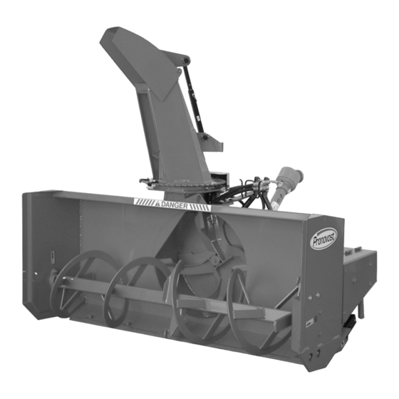
- Page 1 OPERATOR'S / PARTS MANUAL Snowblowers Models P-540 P-620 P-680 & P-680TRC P-720 & P-720TRC P-720-74 P-720-80 No. C278R1 06/07...
- Page 2 Copyright © Les Machineries Pronovost Inc., 2007 All rights reserved. Printed in Canada.
-
Page 3: Table Of Contents
Maintenance ......................14 Storage ........................15 Trouble Shooting ...................... 16 Specifications......................18 Parts List ........................19 Snowblowers P-540, P-620 ................19 Snowblowers P-680, P-720 ................22 Snowblowers P-680TRC, P-720TRC ............. 25 Snowblowers P-720-74, P-720-80 ..............28 Manual Chute Kit MR-4864 ................31 Hydraulic Chute Kit: Motor SP-4864 ............. -
Page 5: Introduction
INTRODUCTION CONGRATULATIONS! Thank you for choosing PRONOVOST. We are NOW take a moment to enter the model, serial confident this equipment will meet your requirements number and the date of purchase of your Snowblower in terms of quality, performance and reliability. -
Page 6: Safety
SAFETY GENERAL SAFETY WHEN YOU SEE THIS SYMBOL 8) Prolonged exposure to noise may hamper hearing. Protect yourself by wearing adequate protection devices. 9) Hydraulic fluids under pressure can damage your skin. Do not use your hands to locate a leak. 10) Before the beginning of the snow season, inspect all areas where the Snowblower will be used and remove any object which may cause an accident and/or damage... -
Page 7: Safety With Maintenance
SAFETY (cont'd) 2) Stop engine and relieve all hydraulic pressures before 10) Before unplugging the chute, always disengage the doing inspection, maintenance or repairs. P.T.O., stop the engine and relieve all hydraulic pressu- res. 3) Never perform any work under the Snowblower while it is supported only by the tractor's hydraulic system. -
Page 8: Decals
DECALS SAFETY DECALS The safety decals are affixed wherever special safety precautions are indicated. Locate them on the machine and read them carefully. If a decal is damaged, lost or illegible, install a new one. The following photos indicate where each one must be installed. Figure 3 Figure 4 Decal B... - Page 9 DECALS (cont'd) Figure 6 Decal C Part no.: A107 Figure 7 Decal D Part no.: A103 Figure 8 Decal E in Fig. 9 is located directly on the P.T.O. shaft. It is not visible when the safety shield is in place.
-
Page 10: Maintenance Decals
DECALS (cont'd) Figure 12 Part no.: A 105 Figure 13 Part no.: A 106 Figure 10 Decal F Part no.: A 109 Figure 14 Decal G Part no.: A104 Figure 11 MAINTENANCE DECALS The maintenance decals indicate the points requiring lubrication. - Page 11 DECALS (cont'd) Figure 18 Decal J Part no.: 190-07611 Figure 16 Decal H Part no.: 190-06651 Figure 19 Figure 17 - 11 -...
-
Page 12: Assembly
ASSEMBLY ASSEMBLY 1) The Snowblower is shipped partly assembled. 2) Install 3-point system according to the model of your Snowblower. (See section 10 for parts numbers). Use the holes most convenient to the type of tractor used (Fig. 18). 3) Install P.T.O. shaft with the shear pin end onto the Snowblower gear box (Fig. -
Page 13: Start-Up
STARTING-UP START-UP PROCEDURES 1) Check oil level in gearbox. Use SAE 80W90 gear box oil. 2) Lubricate all points with a good quality multipurpose grease. 3) Check chain take-up adjustment. The spring maintaining the tension must be compressed to a length between 3"... -
Page 14: Maintenance
MAINTENANCE 1) Wipe off all grease fittings with a clean cloth 7) Check tension of drive chain every 24 hours of before adding grease in order to avoid injecting operation and adjust if necessary. dirt and sand. 8) Check for tightness of bearing collars every 48 2) Repair or replace damaged grease fittings. -
Page 15: Storage
STORAGE 1) Store the Snowblower in a cool, dry place. 5) Thoroughly inspect all parts of the Snowblower. Replace or repair worn or defective parts. 2) Support the Snowblower with wooden blocks. 6) Touch-up or repaint if necessary. 3) Keep all piston rods in the retracted position. This will assure better protection against the elements. -
Page 16: Troubleshooting
TROUBLESHOOTING P.T.O. SHAFT PROBLEM POSSIBLE CAUSE CORRECTION - Premature wear of U-joints and/ - Insufficient lubrication. - Follow lubrication or bluish color of cross journals. recommendations. - Replace defective U-joints. - Excessive working angle. - Make sure the Snowblower inlet face is perpendicular to the ground and if possible readjust 3-point hitch in order to position... - Page 17 TROUBLESHOOTING (cont'd) SNOWBLOWER PROBLEM POSSIBLE CAUSE CORRECTION - Raise P.T.O. speed to a minimum - The snow is not being thrown as - Tractor RPM too low. of 540 RPM. far as usual. - Adjust impeller blades closer to - Gap too wide between impeller drum outlet (1/8"...
-
Page 18: Specifications
SPECIFICATIONS GROUP I P-540 P-620 P-680 P-720 P-720 P-720 Snowblower model P-680 P-720 Snowblower model (HP) min.-max. 18 to 25 20 to 30 25 to 40 25 to 50 30 to 55 30 to 55 Horse power recommended Working width in. -
Page 19: Parts List
SNOWBLOWERS P-540 P-620 170-04411R1 - 19 -... - Page 20 SNOWBLOWERS P-540 P-620 (cont'd) REF. PART # DESCRIPTION 140-01251 Scraper blade (not reversible) 3/8" x 2½" x 50¼" lg ..........140-01261 Scraper blade (not reversible) 3/8" x 2½" x 58¼" lg ..........319-38310 Plow bolt 7/16" NC x 1½" lg + nut & lock washer ..........
- Page 21 SNOWBLOWERS P-540 P-620 (cont'd) REF. PART # DESCRIPTION 300-36280 Bolt 3/8" NC x 1¼" lg + two-way locknut ............6288 Sprocket 50 A36 T 1" ø ..................6281 Auger P-540 ....................6282 Auger P-620 ....................120-01502 Chute (for model PSI-5472 see page 33) ............. opt. opt.
-
Page 22: Snowblowers P-680 P-720
SNOWBLOWERS P-680 P-720 170-04391R1 - 22 -... - Page 23 SNOWBLOWERS P-680 P-720 (cont'd) REF. PART # DESCRIPTION 140-01271 Scraper blade (not reversible) 3/8" x 2½" x 76¼" lg ..........140-01281 Scraper blade (not reversible) 3/8" x 2½" x 68¼" lg ..........319-38310 Plow bolt 7/16" NC x 1½" lg + nut & lock washer ..........110-05541 Skid shoe (right side) ..................
- Page 24 SNOWBLOWERS P-680 P-720 (cont'd) REF. PART # DESCRIPTION FD207 Flange for two grease fittings ................UC207-20 Bearing 1 1/4" ....................300-38310 Bolt 7/16" NC x 1 1/2" lg + two-way locknut ............. 8021 Sprocket 60 A38 T 1 1/4" ø ................110-18842 Auger P-680 ....................
-
Page 25: Snowblowers P-680Trc P-720Trc
SNOWBLOWERS P-680TRC P-720TRC 170-02959R1 - 25 -... - Page 26 SNOWBLOWERS P-680TRC P-720TRC (cont'd) REF. PART # DESCRIPTION 140-01271 Scraper blade (not reversible) 3/8" x 2½" x 64¼" lg ..........140-01281 Scraper blade (not reversible) 3/8" x 2½" x 68¼" lg ..........319-38310 Plow bolt 7/16" NC x 1½" lg + nut & lock washer ..........110-05541 Skid shoe (right side) ..................
- Page 27 SNOWBLOWERS P-680TRC P-720TRC (cont'd) REF. PART # DESCRIPTION 300-40340 Bolt 1/2" NC x 3 1/2" lg + nylon locknut ............110-34201 Chain guard cover ..................... 110-34211 Chain guard cover ..................... 8374 Adjustable clamp fastener (welded) ..............110-18952 Chain guard ...................... 300-40340 Bolt 1/2"...
-
Page 28: Snowblowers P-720-74, P-720-80
SNOWBLOWERS P-720-74 P-720-80 170-03963R1 - 28 -... - Page 29 SNOWBLOWERS P-720-74 P-720-80 (cont'd) REF. PART # DESCRIPTION 140-11181 Scraper blade (not reversible) 3/8" x 2½" x 70¼" lg ..........140-14131 Scraper blade (not reversible) 3/8" x 2½" x 70¼" lg ..........319-38310 Plow bolt 7/16" NC x 1½" lg + nut & lock washer ..........110-05541 Skid shoe (right side) ..................
- Page 30 SNOWBLOWERS P-720-74 P-720-80 (cont'd) REF. PART # DESCRIPTION FD207 Flange for two grease fittings ................UC207-20 Bearing 1 1/4" ....................300-38310 Bolt 7/16" NC x 1 1/2" lg + two-way locknut ............. 8021 Sprocket 60 A38 T 1 1/4" ø ................110-19002 Auger P-720-74 ....................
-
Page 31: Manual Chute Kit Mr-4864
MANUAL CHUTE KIT MR-4864 170-01293 REF. PART # DESCRIPTION Std. Roll pin 1/4" x 1 1/2" ................. 130-09091 Crank stopper ................... 300-38310 Bolt 7/16" NC x 1 1/2" lg + nylon locknut & flat washer ....... 110-08061 Crank ....................... 110-08071 Crank support ................... -
Page 32: Hydraulic Chute Kit: Motor Sp-4864
HYDRAULIC CHUTE KIT SP-4864 Motor 170-01303 REF. PART # DESCRIPTION 300-32220 Bolt 1/4" NC x 3/4" lg + locknut ..............110-04183 Sprocket (9 teeth) ..................323-36160 Allen set screw 3/8" NC x 3/8" lg ............... 300-38280 Bolt 7/16" NC x 1 1/2" lg + nylon locknut & flat washer ......... 300-36250 Bolt 3/8"... -
Page 33: Semi-Industrial Chute Psig-5472
SEMI-INDUSTRIAL CHUTE PSIG-5472 170-04731 REF. PART # DESCRIPTION 110-22861 Upper chute deflector ................. 110-22871 Lower chute deflector ................110-36761 Chute base ....................140-14171 Connecting rod ..................150-05391 Spacer for connecting rod ................Std. Grease fitting 1/4" - 28 droit ............... 378-36500 washer ..................... -
Page 34: Options
OPTIONS 170-02983 - 34 -... - Page 35 OPTIONS (cont'd) REF. PART # DESCRIPTION Semi-industrial scraper blade, carbon steel, not reversible, not sharpened 140-12281 1/2" x 3" x 50 1/4" ............140-12271 1/2" x 3" x 58 1/4" ............140-05801 1/2" x 3" x 64 1/4" ............140-05791 1/2"...
-
Page 36: P.t.o. Shaft # 6408-E
P.T.O. SHAFT # 6408-E (T20) REF. PART # DESCRIPTION 6201 Quick disconnect shear yoke assembly ..............6208 U-joint + 4 retaining rings + 1 grease fitting ............. 6203 Retaining ring ......................8110 Grease fitting ......................6434 Yoke for inner tube ....................6433 Stopper for inner tube ..................... -
Page 37: P.t.o. Shaft # 6248-Eg
P.T.O. SHAFT # 6248-EG (T40) REF. PART # DESCRIPTION 6232-2 Safety shear yoke (2 bolts) ..................6239 U-joint + 4 retaining rings + 1 grease fitting ............. 6234 Retaining ring ......................8110 Grease fitting ......................6353 Yoke for inner tube ....................6344 Stopper for inner tube ..................... -
Page 38: P.t.o. Shaft # 8114-Eg
P.T.O. SHAFT # 8114-EG (T50) REF. PART # DESCRIPTION 8221 Safety shear yoke (2 bolts) ..................8073 U joint + 4 retaining rings + 1 grease fitting ............. 8061 Retaining ring ......................8110 Grease fitting ......................8079 Yoke for inner tube ....................6341 Stopper for inner tube ..................... -
Page 39: Gear Box 6451
GEAR BOX # 6451 (T281) REF. PART # DESCRIPTION 6414 Casing ........................6429 Side shaft (1¼" - 19 splines) ................... 6416 Spacer 35,3 x 48 ....................6207-2RS Ball bearing ......................6418 Key 10 x 8 x 30 ..................... 6419 Impeller shaft (1¼" & 1 3/8" - 6 splines) ..............6420 Seal 35 x 52 x 7 .................... -
Page 40: Gear Box 8251
GEAR BOX # 8251 (T27D) REF. PART # DESCRIPTION 8043 Casing ........................30208-A Roller bearing ......................8045 Inside circlip 80mm ....................8046 Oil seal 40 x 80 x 12mm ..................8047 Adjusting washer ....................8048 Gear Z18 ....................... 8049 Outside circlip 40mm ....................30207-A Roller bearing no. -
Page 41: Cylinder 25Tr04
CYLINDER 25TR04 170-02141 14 ¼" REF. PART # DESCRIPTION 1 See #RK25TR O-ring 1/8" x 2¼" x 2½" ................2 See #RK25TR Back-up 2½" o.d. x 3/16 ø ................. 3 See #RK25TR O-ring 3/16" x 2 1/8" x 2½" ............... 4 See #RK25TR O-ring 1/16"... -
Page 42: Hydraulic Motor Mlh100, Mlh125 & Mlh250
HYDRAULIC MOTOR MLH100, MLH125 & MLH250 CUSHION VALVE H110 MOTOR REF. PART # DESCRIPTION 8368 Set of seals ....................8369 Key for "Orbit" motor ................. - 42 -... -
Page 43: Torque Chart
TORQUE CHART TORQUE SPECIFICATION TABLE Thread UNC and UNF Grade 2 Grade 5 Grade 8* Bolt size Torque Torque Torque Pound feet Newton meters Pound feet Newton meters Pound feet Newton meters Inches min. max. min. max. min. max. min. max. -
Page 44: Warranty
Transportation charges are the responsibility of the Our obligation is limited to the replacement or repair customer. This warranty is not transferable. of the defective part. PRONOVOST accepts no res- ponsibility for direct or indirect consequential dama- Hydraulic cylinders and motors are covered by the ges of any kind. - Page 48 Ce manuel est aussi disponible en français. Veuillez téléphoner. INNOVATION - EXCELLENCE LES MACHINERIES PRONOVOST INC. 260, route 159, Saint-Tite, Quebec, Canada, G0X 3H0 Tel.: (418) 365-7551, Fax: (418) 365-7954 www.pronovost.qc.ca...
Need help?
Do you have a question about the P-540 and is the answer not in the manual?
Questions and answers