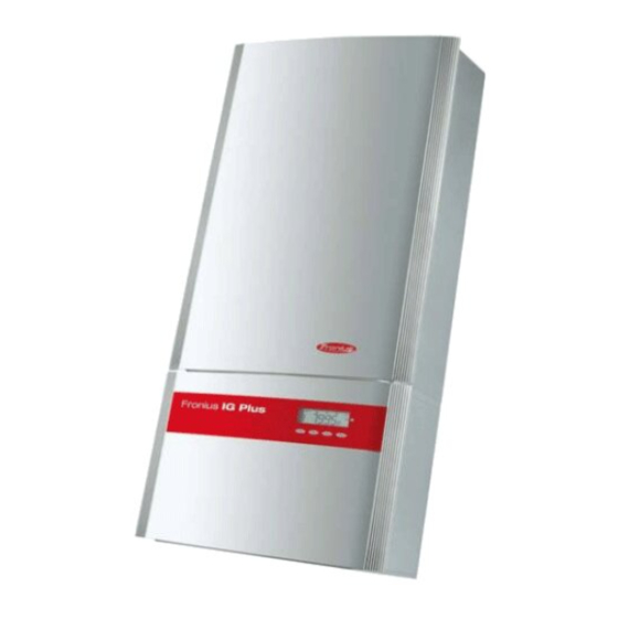
Fronius  IG Plus 35 Operating Instructions Manual

Fronius IG Plus 35 Operating Instructions Manual

Solar power inverters
Table of Contents

Advertisement

Fronius IG Plus
35 / 50 / 70 / 100 / 120 / 150
42,0426,0062,EA 022009
GB
Operating Instructions
Inverter for grid-connected
photovoltaic systems

Advertisement

Table of Contents
loading

Summary of Contents for Fronius Fronius IG Plus 35

  • Page 1 Fronius IG Plus Operating Instructions 35 / 50 / 70 / 100 / 120 / 150 Inverter for grid-connected photovoltaic systems 42,0426,0062,EA 022009...
  • Page 3 Fronius product. This introduction should provide you with general information about the equipment. Please read it carefully to learn about the many great features of your new Fronius product. This is the best way to get the most out of all the advantages that it has to offer.
  • Page 4 ud_fr_st_et_01382 012008...
  • Page 5: Safety Instructions

    Safety Instructions DANGER! “DANGER!“ indicates an imminently hazardous situation which, if not avoided, will result in death or serious injury. WARNING! “WARNING!“ indicates a potentially hazardous situation which, if not avoided, will result in death or serious injury. CAUTION! “CAUTION!“ indicates a potentially harmful situation which, if not avoided, may result in minor and moderate injury or property damage.
  • Page 6 General For information about where the safety instructions and warning signs are (continued) located on the equipment, please refer to the “General“ section of your equipment’s operating instructions. Any equipment malfunctions which might impair safety must be remedied immediately before the device is turned on. Your safety is at stake.
  • Page 7 Safety Precauti- When installing devices with air vents, make sure that cool air can flow freely through the ons at Equipment vents unobstructed. The device should only be operated in accordance with the protec- Location tion class listed on the rating plate. Information on The inverter generates a maximum sound power level of <80dB(A) (ref.
  • Page 8 Electrical Installa- Electrical installations may only be carried out in accordance with relevant tions national and local standards and regulations. ESD Precautions Danger of damage to electronic components due to electrostatic discharge. Take appropriate ESD precautions when replacing and installing compon- ents.
  • Page 9: Table Of Contents

    Fronius IG Plus Installation ....................22 Attaching Wall Bracket ....................22 Fronius IG Plus Installation ..................23 Connecting the Fronius IG Plus to the Public Grid (AC) ..........24 Monitoring the Mains Network ..................24 Installations with Several Inverters ................24 AC-side Terminals ......................
  • Page 10 Connecting Solar Module Strings to the Fronius IG Plus (DC) ........27 General Information About Solar Modules ..............27 Safety........................... 27 DC-Terminals ....................... 28 Connecting Aluminum Cables ..................28 Overview ........................29 Ungrounded System: Connecting Solar Module Strings ..........30 Cable Cross Section of Solar Module Strings ..............
  • Page 11 Solar Module Ground at Positive Pole: Connecting Solar Module Strings with a Cable Cross Section > 16 mm² ....................57 Solar Module Ground at Positive Pole for Fronius IG Plus ..........60 General ........................60 Solar Module Ground at Positive Pole ................. 60 Solar Module Ground at Positive Pole for Fronius IG Plus ..........
  • Page 12 Display of Status Messages ..................113 General Status Messages ................... 113 Total failure ......................... 113 Status Messages for a Fronius IG Plus with Several Power Modules ......114 Status Messages - Class 1 ..................115 Status Messages - Class 3 ..................117 Status Messages - Class 4 ..................
  • Page 13 Maintenance ........................129 Safety......................... 129 General ........................129 Operation in Environments with a Strong Formation of Dust ........129 Opening Fronius IG Plus for Service/Maintenance ............ 130 Replacing String Fuses ....................131 Safety......................... 131 Before Installing ......................131 Replacing Fuses ......................132 Finally...
  • Page 15: General Information

    General Information...
  • Page 17: Operator And Equipment Protection

    Galvanic Isola- The Fronius IG Plus is equipped with a high frequency transformer that tion provides galvanic isolation between the DC side and the grid, thus ensu- ring the highest possible safety.
  • Page 18: The Fronius Ig Plus In The Photovoltaic System

    The Fronius IG Plus operates in such a way as to ensure that the maxi- mum power possible is obtained from the solar modules. This function is called „Maximum Power Point Tracking“ (MPPT).
  • Page 19: System Upgrades

    Fronius IG Plus (e.g. in switch boxes that do not have an appropriate heat dissipation system). A power derating system briefly restricts the output from the Fronius IG Plus in order to prevent the temperature from exceeding the permissible value.
  • Page 21: Installation And Startup

    Installation and Startup...
  • Page 23: Fronius Ig Plus Installation And Connection

    Connection area and power module on the Fronius IG Plus Overview ‘Fronius IG Plus Installation and Connection’ contains the following sec- tions: Fronius IG Plus Connection Options Target Punch-outs on the Fronius IG Plus Location Selection...
  • Page 24: Fronius Ig Plus Connection Options

    (13) (18) (17) (16) (15) (14) Connections on the Fronius IG Plus Item Description Fuse cover (6 x for string fuses, 1 x for the solar module ground fuse) Jumper slot SM DC- main switch cable 6 DC+ fuse holders...
  • Page 25 Fronius IG Item Description Plus Connec- (14) Metric screw joint M32 or M40 (AC connection) tion Options (15) 6 DC- terminals (continued) (16) Strain relief device for solar module strings (17) 6 DC+ terminals (18) DC main switch...
  • Page 26: Target Punch-Outs On The Fronius Ig Plus

    Target Punch- outs for Cable Inputs Target punch-outs on the back and inside base of the Fronius IG Plus Item Description 4 back cable inputs: Diameter 34.5 / 28 and 28 / 22.5 mm Cable openings that lead through the back to the inverter...
  • Page 27 Target Punch- NOTE outs for Cable The target punch-outs made from plastic as well as the larger Inputs ones made from metal should only be removed from the (continued) outside in. The smaller target punch-outs made from metal should be removed from the inside out.
  • Page 28: Location Selection

    The air flow direction within the inverter runs from right to left (cold air intake right, warm air exhaust left). If the Fronius IG Plus is installed in a switch box (or similar enclosed area), then forced-air ventilation must be provided to ensure adequate heat dissipation.
  • Page 29: Location Selection For Inside Installation

    Location Se- Do not install the Fronius IG Plus near living areas because it may emit a lection for small amount of noise under certain operating conditions. Inside Installa- Do not install the Fronius IG Plus in: tion Rooms with a large formation of dust Rooms with a large formation of dust with conductive particles (e.g.
  • Page 30: Fronius Ig Plus Installation

    Bracket be required for installing the wall bracket. These dowels and screws are not part of the scope of delivery for the Fronius IG Plus. The installer is responsible for selecting the proper dowels and screws. NOTE The Fronius IG Plus should only be installed upright on the wall.
  • Page 31: Fronius Ig Plus Installation

    Fronius IG NOTE For Fronius IG Plus assembly, please ensure that: Plus Installati- the wall bracket is fixed securely to the wall the connector is hung and fixed to the wall bracket the power module is hung on the wall bracket and fixed to the...
  • Page 32: Connecting The Fronius Ig Plus To The Public Grid (Ac)

    Installations For large photovoltaic systems, several Fronius IG Plus units can be with Several connected in parallel. Inverters To ensure symmetrical feeding, connect the inverters uniformly to all 3 phases.
  • Page 33: Connecting Aluminum Cables

    The separate power module area should only be opened by Fronius-trained service personnel. Before making any connections, make sure that the AC and DC sides are disconnected from the inverter.
  • Page 34: Connecting The Fronius Ig Plus To The Public Grid (Ac)

    Fronius IG Plus 150 - 3 12 kW 3 x C 25 A NOTE Only for Fronius IG Plus 150: When using an FI circuit breaker, the voltage difference between the PE conductor and the N neutral conductor cannot be higher than 8 V.
  • Page 35: Connecting Solar Module Strings To The Fronius Ig Plus (Dc)

    If insolation is constant and the temperature is falling, the open-circuit voltage of the solar modules will increase. Open-circuit voltage may not exceed 600 V. Open-circuit voltage over 600 V will damage the Fronius IG Plus voiding the warranty. More exact values for dimensioning solar modules for the chosen installation location can be provided using suitable calculation pro- grams like the Fronius Solar.configurator (available at...
  • Page 36: Dc-Terminals

    DC-Terminals DC+ and DC- terminals on the Fronius IG Plus The DC side terminals are designed for connecting single-wire, Connecting round and sector-pattern aluminum cables. Aluminum The following points must be taken into account when connecting alumi- Cables num cables due to the non-conducting oxide layer of aluminum:...
  • Page 37: Overview

    Overview ‘Connecting Solar Module Strings to the Fronius IG Plus (DC)’ includes the following sections: Ungrounded System: Connecting Solar Module Strings Criteria for the Proper Selection of String Fuses Ungrounded System: Connecting Solar Module Strings with a Cable Cross Section > 16 mm²...
  • Page 38: Ungrounded System: Connecting Solar Module Strings

    Ungrounded System: Connecting Solar Module Strings The cable cross section for solar module strings should be a maximum Cable Cross of 16 mm² per cable. Section of Solar Module Strings Ungrounded System: Con- necting Solar Module Strings 10mm...
  • Page 39 The metal bolts are included in the Fronius IG Plus scope of delivery. Place metal bolts with fuse covers in the fuse holders for unoccupied...
  • Page 40: Selecting String Fuses

    Fuses in Fro- fuses: nius IG Plus Insert fuses with a fuse cover in the respective fuse holder Do not operate the Fronius IG Plus without fuse covers WARNING! An electrical shock can be fatal. Danger from DC voltage from solar modules.
  • Page 41: Criteria For The Proper Selection Of String Fuses

    Criteria for the Proper Selection of String Fuses General The use of string fuses in the inverter also adds fuse protection to the solar modules. A crucial factor for the fuse protection of solar modules is the maximum short circuit current (I or STC) of the respective solar module.
  • Page 42: Fuses

    Fuses Nominal Nominal current value Fuse current value Fuse 1.0 A KLK D 1 6.0 A KLK D 6 1.5 A KLK D 1 7.0 A KLK D 7 2.0 A KLK D 2 8.0 A KLK D 8 2.5 A KLK D 2 9.0 A KLK D 9...
  • Page 43: Ungrounded System: Connecting Solar Module Strings With A Cable Cross Section > 16 Mm²

    Strings with a Cable Cross Section > 16 mm² General As an option, you can also connect DC cables to the Fronius IG Plus with a cross section > 16 mm², e.g. when the DC cables from the solar modu- les are combined outside of the inverter leads into a large string.
  • Page 44 Ungrounded System: Con- necting Solar Module Strings with a Cable Cross Section > 16 mm² (continued) CAUTION! Danger of damaging the inverter by overload. Connect the DC+ and DC- cables to the correct DC+ and DC- terminals on the inverter. Tightening torque 1,2 - 1,5 Nm Tightening torque 1,2 - 1,5 Nm...
  • Page 45 Check the polarity and voltage of the DC cable: the voltage should be a max. of 600 V. max. 600 V Important When using connection distributors (copper plate), insert 6 metal bolts with fuse covers in the fuse holder. The metal bolts are included in the Fronius IG Plus scope of delivery.
  • Page 46: Solar Module Ground At Negative Pole: Connecting Solar Module Strings

    Solar Module Ground at Negative Pole: Connec- ting Solar Module Strings General The following working steps are only necessary when the solar module manufacturer requires a solar module ground at the negative pole. The cable cross section for solar module strings should be a maximum Cable Cross of 16 mm²...
  • Page 47 The metal bolts are included in the Fronius IG Plus scope of delivery. Place metal bolts with fuse covers in the fuse holders for unoccupied...
  • Page 48: Selecting String Fuses

    Fuses in Fro- fuses: nius IG Plus Insert fuses with a fuse cover in the respective fuse holder Do not operate the Fronius IG Plus without fuse covers WARNING! An electrical shock can be fatal. Danger from DC voltage from solar modules.
  • Page 49: Criteria For The Proper Selection Of String Fuses

    Criteria for the Proper Selection of String Fuses General The use of string fuses in the inverter also adds fuse protection to the solar modules. A crucial factor for the fuse protection of solar modules is the maximum short circuit current (I or STC) of the respective solar module.
  • Page 50: Fuses

    Fuses Nominal Nominal current value Fuse current value Fuse 1.0 A KLK D 1 6.0 A KLK D 6 1.5 A KLK D 1 7.0 A KLK D 7 2.0 A KLK D 2 8.0 A KLK D 8 2.5 A KLK D 2 9.0 A KLK D 9...
  • Page 51: Solar Module Ground At Negative Pole: Connecting Solar Module Strings With A Cable Cross Section > 16 Mm²

    As an option, you can also connect DC cables to the Fronius IG Plus with a cross section > 16 mm², e.g. when the DC cables from the solar modu- les are combined outside of the inverter leads into a large string.
  • Page 52: Solar Module Ground At Negative Pole: Connecting Solar Module Strings With A Cable Cross Section > 16 Mm²

    Solar Module Ground at Negative Pole: Connecting Solar Module Strings with a Cable Cross Section > 16 mm² CAUTION! Danger of damaging the inverter by overload. Connect the DC+ and DC- cables to the correct DC+ and DC- terminals on the inverter. Tightening torque 1,2 - 1,5 Nm...
  • Page 53: Solar Module Ground At Negative Pole: Connecting Solar Module Strings With A Cable Cross Section > 16 Mm²

    Solar Module Ground at Negative Pole: Connecting Solar Module Strings with a Cable Cross Section > 16 mm² Tightening torque 1,2 - 1,5 Nm Important Set the jumper from the ‘SM ’ position to the ‘SM ’ position for correct measurement results Check the polarity and voltage of the DC cable: the voltage should be a max.
  • Page 54 Important When using connection distributors, insert 6 metal bolts with Ground at fuse covers in the fuse holder. Negative Pole: The metal bolts are included in the Fronius IG Plus scope of delivery. Connecting Solar Module Strings with a Cable Cross Section >...
  • Page 55: Solar Module Ground At Negative Pole For Fronius Ig Plus

    Negative Pole Example: Solar module ground at negative pole with fuse Solar Module You can ground solar modules in the Fronius IG Plus using a fuse. Ground at Fronius recommends a fuse with 1 Negative Pole A and a dimension of 10 x 38 mm for Fronius IG for solar module grounding.
  • Page 56: Safety

    A code is required to access the 2nd level of the Setup menu. This code can be requested from Fronius. Additional information regar- ding accessing the 2nd level of the Setup menu will be provided along with the code.
  • Page 57: Opening Fronius Ig Plus For Service/Maintenance

    Inserting the fuse will ground the solar module at the negative pole. Opening Fro- Procedure for opening the Fronius IG Plus for service or maintenance: nius IG Plus for Service/ 1. Disconnect the AC and DC sides from the inverter Maintenance 2.
  • Page 58: Solar Module Ground At Positive Pole: Connecting Solar Module Strings

    Solar Module Ground at Positive Pole: Connec- ting Solar Module Strings General The following work step is only necessary when the solar module manuf- acturer requires a solar module ground at the positive pole. The cable cross section for solar module strings should be a maximum Cable Cross of 16 mm²...
  • Page 59 Solar Module Ground at Positive Pole: Connecting 10mm Solar Module Strings (continued) After disconnecting the DC main switch cable: Connect the DC+ cable to the DC- connection as per work step 5 Connect the DC- cable to the DC+ connection as per work step 5 NOTE Identify the reversed polarity accordingly with (+) and (-).
  • Page 60: Selecting String Fuses

    The metal bolts are included in the Fronius IG Plus scope of delivery. Place metal bolts with fuse covers in the fuse holders for unoccupied DC+ terminals.
  • Page 61: Using String Fuses In Fronius Ig Plus

    IG Plus Insert fuses with a fuse cover in the respective fuse holder Do not operate the Fronius IG Plus without fuse covers WARNING! An electrical shock can be fatal. Danger from DC voltage from solar modules. Fuse covers are for installation purposes only. They offer no...
  • Page 62: Criteria For The Proper Selection Of String Fuses

    Criteria for the Proper Selection of String Fuses General The use of string fuses in the inverter also adds fuse protection to the solar modules. A crucial factor for the fuse protection of solar modules is the maximum short circuit current (I or STC) of the respective solar module.
  • Page 63: Fuses

    Fuses Nominal Nominal current value Fuse current value Fuse 1.0 A KLK D 1 6.0 A KLK D 6 1.5 A KLK D 1 7.0 A KLK D 7 2.0 A KLK D 2 8.0 A KLK D 8 2.5 A KLK D 2 9.0 A KLK D 9...
  • Page 64: Solar Module Ground At Positive Pole: Connecting Solar Module Strings With A Cable Cross Section > 16 Mm²

    As an option, you can also connect DC cables to the Fronius IG Plus with a cross section > 16 mm², e.g. when the DC cables from the solar modu- les are combined outside of the inverter leads into a large string.
  • Page 65: Solar Module Ground At Positive Pole: Connecting Solar Module Strings With A Cable Cross Section > 16 Mm²

    Solar Module Ground at Positive Pole: Connecting Solar Module Strings with a Cable Cross Section > 16 mm² After disconnecting the DC main switch cable: Connect the DC+ cable to the DC- connection as per work step 5 Connect the DC- cable to the DC+ connection as per work step 5 NOTE Identify the reversed polarity accordingly with (+) and (-).
  • Page 66 Solar Module CAUTION! Danger of damaging the inverter by overload. Ground at Connect the DC+ cable to the right connection of the Positive Pole: inverter’s DC terminal. Connecting Connect the DC- cable to the left connection of the Solar Module inverter’s DC terminal.
  • Page 67 Cable Cross Section > 16 mm² max. 600 V (continued) Important! When using connection distributors (copper plate), insert 6 metal bolts with fuse covers in the fuse holder. The metal bolts are included in the Fronius IG Plus scope of delivery.
  • Page 68: Solar Module Ground At Positive Pole For Fronius Ig Plus

    Example: Solar module ground at positive pole with fuse Solar Module You can ground solar modules in the Fronius IG Plus using a fuse. Ground at Fronius recommends a fuse with 1 Positive Pole A and a dimension of 10 x 38 mm for Fronius IG for solar module grounding.
  • Page 69: Safety

    A code is required to access the 2nd level of the Setup menu. This code can be requested from Fronius. Additional information regar- ding accessing the 2nd level of the Setup menu will be provided along with the code.
  • Page 70: Opening Fronius Ig Plus For Service/Maintenance

    Inserting the fuse will ground the solar module at the positive pole. Opening Fro- Procedure for opening the Fronius IG Plus for service or maintenance: nius IG Plus for Service/ 1. Disconnect the AC and DC sides from the inverter Maintenance 2.
  • Page 71: Closing Fronius Ig Plus

    Closing Fronius IG Plus Closing Froni- us IG Plus...
  • Page 72: Inserting Option Cards

    Various large displays (public display) Actuators / relays / alarms (signal card) Sensors (temperature / insolation / energy meter) System upgrades come in the form of plug-in cards. The Fronius IG Plus can be equipped with three option cards. Safety WARNING! An electrical shock can be fatal.
  • Page 73: Inserting Option Cards

    Inserting Option Cards Important Depending on the number of option card cables, please use corresponding square sealing inserts. Square sealing inserts are part of the option card scope of delivery. The round sealing insert is included in the ‘COM card’ option scope of delivery.
  • Page 74: Solar Net And Data Interface

    Important Each inverter can only have one ‘COM card.’ A network may only contain one Datalogger. The first Fronius IG Plus with a ‘COM card’ can be up to 1000 m (3280 ft) away from the last Fronius IG Plus with a ‘COM card.’...
  • Page 75: Example

    °C W/m² Termination plug Data network with 3 Fronius IG Plus units and one sensor box: - all Fronius IG Plus units have one ‘COM Card’ - one Fronius IG Plus has a ‘Datalogger card’ (no. 2) - Datalogger has two RS-232 interfaces for connecting to a PC and a modem Option cards communicate within the Fronius IG Plus via its internal net- work.
  • Page 76: Commissioning

    Commissioning Factory Confi- The Fronius IG Plus has been pre-configured at the factory and is ready guration to use. You can assign individual numbers as per ‘The Setup Menu’ section in this manual. Commissio- Once the Fronius IG Plus has been connected to the solar modules (DC) ning and the public grid (AC), turn the main switch to position - 1 -.
  • Page 77: Operation

    Operation...
  • Page 79: Fronius Ig Plus Device Description

    Power for the display comes from the solar modules via safety-low volta- ge. The display is therefore available during daylight hours. Important The Fronius IG Plus display is not an aligned measuring instru- ment. A slight deviation of a few percent points is intrinsic to the system.
  • Page 80 ... appears when displaying values associated with envi- ronmental conditions such as solar radiation and tempera- ture (optional) ... appears when displaying values directly associated with the public grid ... appears when displaying values directly associated with the Fronius IG Plus...
  • Page 81: Startup Phase

    Startup Phase Once the Fronius IG Plus switches on automatically it runs a self-test. After this, the public grid is tested. This test can take from several seconds up to several minutes depending on local regulations.
  • Page 82 ’ and ‘AUTO ’ TEST 5. Startup test Before the Fronius IG Plus begins feeding power into the grid, grid conditions are tested according to local regulations ‘START ’ will appear on the display The startup test can take anywhere from just a few seconds up to several minutes depending on local regulations.
  • Page 83: Led Operating Status

    Status Explanation lights up green The LED stays lit after the automatic startup phase of the Fronius IG Plus as long as power is being fed into the grid. The photovoltaic system is working correctly. flashing green The photovoltaic system is working correctly, a status message is on the display.
  • Page 84 LED Operating LED Operating Status Status Explanation (continued) lights up red General status: Display of corresponding status message on the Display remains dark No connection to solar modules No output from module due to an absence of daylight A list of corresponding status messages, causes, and troubleshooting measures can be found in ‘Maintenance and Service’...
  • Page 85: Navigating Around The Display

    1. Press the „Menu“ button (1) Menus Accessing Menus ‘Menu’ will appear on the dis- play The Fronius IG Plus is now in the menu level. From the menu level you can set the desired display mode access the Setup menu...
  • Page 86: Selecting A Display Mode

    Selecting a 1. Accessing Menu Levels display mode 2. Use the ‘left (7) or ‘right’ (6) (1) (2) (3) (4) keys to select your preferred display mode (1) - (4) 3. Press ‘Enter’ (5) Selecting a Display Mode The selected display mode is shown Important The ‘Year’...
  • Page 87: Overview Of Display Values

    Min. solar module temperature °C / °F Max. ambient temperature °C / °F Min. ambient temperature W/m² Max. solar radiation HH:MM Fronius IG Plus operating hours Optional If the required option card is not available, ‘N.A.’ (not applicable) will be displayed.
  • Page 88: Display Modes

    Display Modes Display Modes The following display modes are available for the Fronius IG Plus: „Now’ display mode ..Displays real-time values ‘Day’ display mode ..Displays values for power fed into the grid during that day ‘Year’ display mode ..Displays values for power fed into the grid during...
  • Page 89: Display Values In 'Now' Display Mode

    ‘Now’ Dis- Power (in watts) currently being fed play Mode into the grid Mains voltage (in volts) Current fed in Current (in amperes) currently being fed into mains Mains frequency (hertz) *) only for a multi-phase Fronius IG Plus...
  • Page 90 DC lead or defective solar modules. In the event that the insulation resistance is too low, you must contact your Fronius service partner. The insulation resistance is the resistance between the positive or negati- ve poles of the photovoltaic system and the ground potential. If an insula- tion resistance >...
  • Page 91: Options

    Insolation power coming down on each square meter (watts/ m²,optional sensor card) Time (optional Datalogger) When the time on the Fronius IG Plus or a system upgrade is chan- ged, this changes the time on all connected devices via Solar Net.
  • Page 92: Display Values In 'Day / Year / Total' Display Mode

    Display Values in ‘Day / Year / Total’ Display Mode General The time when the Fronius IG Plus is turned on signals the start of the day. If the DC-in lead is disconnected, the following values will be reset for the ‘Day’...
  • Page 93: Display Values In 'Day / Year / Total' Display Mode

    Display Values Energy fed into the grid in ‘Day / Year / Energy fed into the grid over the Total’ Display period of time in question (kWh / Mode MWh) There may be discrepancies with values displayed on other measuring instruments because of differences in methods of measurement.
  • Page 94 Display Values Max. mains voltage in ‘Day / Year / highest mains voltage (V) measu- Total’ Display red during the time in question Mode (continued) Min. mains voltage lowest mains voltage (V) measured during the time in question Max. solar module voltage highest solar module voltage (V) measured during the time in questi- Energy recorded by energy me-...
  • Page 95: Options

    The operating hours are shown in hours and minutes up to 999 hours and 59 minutes (‘999:59’). After that, only the hours are shown. Although the Fronius IG Plus does not operate during the night, the data required by the optional sensor card is logged and stored 24 hours a day.
  • Page 96: The Setup Menu

    The Setup Menu Default Set- The Fronius IG Plus is pre-configured and ready to use. There is no need tings to make any initial settings before using it to feed power into the grid. This is a fully-automated process. The Setup menu enables you to change the default settings for the Froni- us IG Plus to meet user specifications and requirements.
  • Page 97: Scrolling Through Menu Options

    Scrolling through Menu Options Example: ‘STAND ’ menu option Example: ‘CONTR ’ menu option 1. Open the setup menu 2. Scroll through the available menu options using the ‘Up’ (1) and ‘Down’ (2) keys Menu Options STAND in the Setup Manual activation / deactivation of Standby operation using the ‘Enter’...
  • Page 98 Menu Options LIGHT MODE in the Setup Initial setting for display illumination. Menu Unit (continued) Setting range AUTO / ON / OFF Factory setting AUTO AUTO: The display illumination is switched off if no key is pressed for 30 seconds. The display illumination remains on permanently while power is being fed into the grid.
  • Page 99 Menu Options IG no. in the Setup Sets the number (= address) of the Fronius IG Plus in a system with Menu several solar inverters (continued) Unit Setting range 01 - 99 (100. Fronius IG Plus = 00) Factory setting Important! Each Fronius IG Plus must be assigned its own address when connecting several inverters in a data communications system.
  • Page 100: Setting And Displaying Menu Options

    1. Select the ‘STAND ’ menu option 2. Press the ‘Enter’ key The Fronius IG Plus will switch to the Startup phase. After a successful startup, the Operating Status LED will be green. The current power feed will be displayed.
  • Page 101: Setting The 'Contrast' Menu Option

    Setting the 1. Select the ‘CONTR ’ menu ‘CONTR ’ option menu option 2. Press the ‘Enter’ key Setting ‘7’ for the highest pos- sible contrast will be displayed 3. Use the ‘Up’ and ‘Down’ keys to select the desired level of cont- rast ‘0’...
  • Page 102: Setting The 'Cash' Menu Option

    Setting the ON ... Display illumination on ‘LIGHT ’ permanently MODE menu option (continued) OFF ... Display illumination turned off 3. Use the ‘Up’ and ‘Down’ keys to select the desired setting for the display illumination 4. Press the ‘Enter’ key to apply the setting 5.
  • Page 103 Setting the The third character will now ‘CASH’ Menu flash Option (continued) 7. Use the ‘Up’ and ‘Down’ keys to select a letter for the third cha- racter 8. Press the ‘Enter’ key The set currency will now flash 9. Press the ‘Enter’ key The charge rate is now display- ed in kWh/currency, factory setting = 0.48 EUR /...
  • Page 104: Setting The 'Co2' Menu Option

    Setting the The second digit after the deci- ‘CASH’ Menu mal point flashes Option (continued) 16. Use the ‘Up’ and ‘Down’ keys to select a value for the second digit after the decimal point (e.g. 8) The values that can be set range from 00.01 to 99.99 17.
  • Page 105: Setting The 'Yield' Menu Option

    Setting the The second digit will now flash ‘CO ’ Menu Option 5. Use the ‘Up’ and ‘Down’ keys to (continued) select a number for the second digit 6. Press the ‘Enter’ key The first digit after the decimal point flashes 7.
  • Page 106 Setting the ‘OFFset’ is displayed ‘YIELD’ Menu Option 3. Press the ‘Enter’ key (continued) The OFF value is displayed, the first digit flashes 3. Use the ‘Up’ and ‘Down’ keys to select a number for the first digit 4. Press the ‘Enter’ key The second digit of the OFF value flashes 5.
  • Page 107 Setting the The character for the unit prefix ‘YIELD’ Menu flashes Option (continued) 13. Use the ‘Up’ or ‘Down’ keys to select a unit prefix: k = 1000 M = 1000000 14. Press the ‘Enter’ key The set OFF value and the unit prefix flashes 15.
  • Page 108: Setting The 'Ig No.' Menu Option

    Setting the The digit after the decimal ‘YIELD’ Menu place flashes Option (continued) 22. Use the ‘Up’ and ‘Down’ keys to select a value for the digit after the decimal place 23. Press the ‘Enter’ key The set correction value flashes 24.
  • Page 109: Setting The 'Datcom' Menu Option

    Setting the ‘IG The set inverter number will No.’ Menu now flash Option (continued) 7. Press the ‘Enter’ key The number has been applied 8. Press the ‘Esc’ key to exit the ‘IG No.’ menu option Setting the 1. Select the ‘DAT ’...
  • Page 110 Setting the 5. Press the ‘Esc’ key to exit the ‘DAT ’ Menu ‘Signal Card Test’ Option (continued) ‘SIGCD ’ will be displayed TEST 6. Use the ‘Down’ key to select additional options: e.g. Rest Personal Display Card (‘PDCD ’) ..
  • Page 111: Setting The 'Time' Menu Option

    Setting the ‘SIGCD ’ (‘Signal Card’ not ‘DAT ’ Menu installed) or Option ‘PDCD ’ (‘Personal Display (continued) Card’ not installed) or ‘IFCD ’ (‘Interface Card’ not installed) will be displayed 4. Press the ‘Esc’ key to exit the ‘DAT ’...
  • Page 112 Setting the The second digit for the month ‘TIME’ Menu flashes Option (continued) 9. Use the ‘Up’ and ‘Down’ keys to select a value for the second month digit 10. Press the ‘Enter’ key The first digit for the year flas- 11.
  • Page 113 Setting the The time is displayed (HH:MM), ‘TIME’ Menu the first digit for the hour flas- Option (continued) 20. Use the ‘Up’ and ‘Down’ keys to select a value for the first hour digit 21. Press the ‘Enter’ key The second digit for the hour flashes 22.
  • Page 114: Displaying The 'Stateps' Menu Option

    Displaying the 1. Select the ‘STATE ’ menu ‘STATE ’ option menu option 2. Press the ‘Enter’ key The status of the first power module PS00 will be displayed, e.g.: STDBY PSOO STDBY = standby (no grid feed) 3. Press the ‘Enter’ key to display the last status message saved The display switches between ‘STATE...
  • Page 115: Displaying The 'Version' Menu Option

    Displaying the The display switches between ‘STATE ’ menu option (continued) ‘STATE ’ LAST the last saved status message. 7. Press the ‘Esc’ key 2x to exit the ‘STATE ’ menu option Displaying the 1. Select the ‘VERSI ’ menu ‘VERSI ’...
  • Page 116 Displaying the The identification number of the ‘VERSI ’ IG Brain unit is displayed menu option (continued) 6. Press ‘Down’ to display the hardware version of the IG Brain unit The hardware version of the IG Brain unit is displayed 7.
  • Page 117 Displaying the The component ID of the se- ‘VERSI ’ lected power module is display- menu option (continued) 13. Press the ‘Down’ key to display the power module identification number The identification number of the selected power module is dis- played 14.
  • Page 119: Troubleshooting And Maintenance

    Troubleshooting and Maintenance...
  • Page 121: Status Diagnosis And Troubleshooting

    Status Diagnosis and Troubleshooting Display of The Fronius IG Plus is able to perform a system self diagnostic that auto- Status Mes- matically detects many errors that may occur and shows them on the sages display. This enables you to know immediately if there are any malfunc- tions in the Fronius IG Plus, the photovoltaic system or any installation or operating errors.
  • Page 122: Status Messages For A Fronius Ig Plus With Several Power Modules

    Status Mes- If an error occurs in a Fronius IG Plus with more than one power module, sages for a then a specific status message will be displayed. Fronius IG Plus with Status messages can also be accessed even when there is no fault.
  • Page 123: Status Messages - Class 1

    Class 1 caused by the public grid. The initial response of the Fronius IG Plus in this case is to disconnect itself from the grid. The grid is then checked for the stipulated monitoring period. If no further problem has been detected by the end of this period, the Fronius IG Plus will resume feeding power into the grid.
  • Page 124 Behavior Grid conditions will be thoroughly tested and as soon (continued) as they are again within the permissible range, the Fronius IG Plus will resume feeding power into the grid. Remedy Check grid connections and fuses If this status message keeps recurring, contact your...
  • Page 125: Status Messages - Class 3

    The Fronius IG Plus disconnects automatically from the grid. The grid is then monitored as specified and the Fronius IG Plus then attempts to resume feeding power.
  • Page 126 ‘POWER ’ (306) Intermediate circuit voltage too low for feed operation, this error is displayed on the Fronius IG Plus in plain text Behavior Short-term interruption of grid feed operation Fronius IG Plus resumes its boot routine Remedy...
  • Page 127: Status Messages - Class 4

    If the status message remains on the display: notify a Fronius-trained service technician One or both temperature sensors are defective Behavior The Fronius IG Plus will disconnect from the grid for safety reasons Remedy If the status message remains on the display: notify a...
  • Page 128 If the status message remains on the display: notify a Fronius-trained service technician Control problems Behavior Because grid conditions have changed significantly, the Fronius IG Plus is disconnected briefly from the grid. Remedy If the status message remains on the display: notify a Fronius-trained service technician...
  • Page 129 Status Messages - PCB number has been set incorrectly Class 4 Behavior The Fronius IG Plus stops feeding power into the (continued) gird, the display shows a critical error via a red Ope- rating Status LED Remedy If the status message remains on the display: notify a...
  • Page 130 Status Messages - Invalid power module configuration Class 4 Behavior The Fronius IG Plus stops feeding power into the (continued) gird, the display shows a critical error via a red Ope- rating Status LED Remedy If the status message remains on the display: notify a Fronius-trained service technician The monitoring of the power module main processor ‘Guard’...
  • Page 131 Reference power source for AC measurement is operating outside of Class 4 tolerances (continued) Behavior The Fronius IG Plus stops feeding power into the gird, the display shows a critical error via a red Ope- rating Status LED Remedy If the status message remains on the display: notify a...
  • Page 132 The UI command sent from the IG Brain is not recognized by the current (continued) display version. Behavior The Fronius IG Plus stops feeding power into the gird, the display shows a critical error via a red Ope- rating Status LED Remedy...
  • Page 133: Status Messages - Class 5

    Insulation value too low Description While automatically measuring the insulation, the Fronius IG Plus has detected an insulation fault to the ground Remedy Check the insulation of your photovoltaic system The status message reappears: Contact your system...
  • Page 134 Status Messages - Communication with Solar Net not possible Class 5 Description Fronius IG Plus address has been assigned twice (continued) Remedy Change Fronius IG Plus address (section: ‘The Setup Menu’) Description The Solar Net components required are in the Froni-...
  • Page 135 Analyze the messages. Additional information can be found in ‘The Setup Menu’ section, STATE ’ menu option. If the status message remains on the display: notify a Fronius-trained service technician Master has been changed. Description Transformer not connected/plugged in Jumper short circuit...
  • Page 136: Customer Service

    Remedy If the status message remains on the display: notify a Fronius-trained service technician Customer Important! Please contact your Fronius dealer or a Fronius-trained ser- Service vice partner if an error appears frequently or for a long period of time...
  • Page 137: Maintenance

    You must wait until the capacitors have discharged. Discharge takes 5 minutes. General The Fronius IG Plus is designed so that it does not require additional maintenance. However, there are a few points to keep in mind during operation to ensu- re that the inverter functions optimally.
  • Page 138: Opening Fronius Ig Plus For Service/Maintenance

    Opening Fro- Procedure for opening the Fronius IG Plus for service or maintenance: nius IG Plus for Service/ 1. Disconnect the AC and DC sides from the inverter Maintenance 2. Open the connection area 3. Turn off DC main switch 4.
  • Page 139: Replacing String Fuses

    Replacing String Fuses Safety WARNING! An electrical shock can be fatal. Danger from mains voltage and DC voltage from solar modules. The connection area should only be opened by a licensed electrician. Before making any connections, make sure that the AC and DC sides are disconnected from the inverter.
  • Page 140: Replacing Fuses

    Replacing Test the fuse holder at the terminal for continuity Fuses NOTE Only use fuses for solar modules that meet the proper requirements for string fuses. Fuse dimensions: Diameter 10.3 x 35 - 38 mm After replacing the fuse: Find out and correct the cause for the defective fuse Finally...
  • Page 141: Appendix

    Appendix...
  • Page 143: Technical Data

    Technical Data Fronius IG Input data Plus 35 MPP voltage range 230 - 500 V DC Max. input voltage 600 V DC (at 1000 W/m²/ -10 °C (14 °F) in an open circuit) Max. input current 16 A DC Output data Nominal output power (P 3.5 kW...
  • Page 144: Fronius Ig Plus 50

    Fronius IG Input data Plus 50 MPP voltage range 230 - 500 V DC Max. input voltage 600 V DC (at 1000 W/m²/ -10 °C (14 °F) in an open circuit) Max. input current 18.3 A DC Output data Nominal output power (P 4 kW Max.
  • Page 145: Fronius Ig Plus 70

    Fronius IG Input data Plus 70 MPP voltage range 230 - 500 V DC Max. input voltage 600 V DC (at 1000 W/m²/ -10 °C (14 °F) in an open circuit) Max. input current 29.7 A DC Output data Nominal output power (P 6.5 kW...
  • Page 146: Fronius Ig Plus 100

    Fronius IG Input data Plus 100 MPP voltage range 230 - 500 V DC Max. input voltage 600 V DC (at 1000 W/m²/ -10 °C (14 °F) in an open circuit) Max. input current 36.6 A DC Output data Nominal output power (P 8 kW Max.
  • Page 147: Fronius Ig Plus 120

    Fronius IG Input data Plus 120 MPP voltage range 230 - 500 V DC Max. input voltage 600 V DC (at 1000 W/m²/ -10 °C (14 °F) in an open circuit) Max. input current 45.78 A DC Output data Nominal output power (P 10 kW Max.
  • Page 148: Fronius Ig Plus 150

    Protection against reversed polarity integrated Manifestation of DC overload Operating point shift Explanation of The values provided are standard values. Upon request, the Fronius footnotes IG Plus can be customized to the respective country. PCC = interface to the public grid...
  • Page 149: Relevant Standards And Directives

    DIN VDE 0126-1-1. Grid Failure The standard measurement and safety procedures integrated into the Fronius IG Plus ensure that the power feed is immediately interrupted in the event of a grid failure (shut-off by the utility or damage to lines). Relevant Stan- „Safety requirements for photovoltaic energy generation plants“...
  • Page 150: Warranty And Disposal

    Warranty and Disposal Warranty The Fronius IG Plus is covered by a warranty in accordance with the Provisions general terms and conditions. During this period, Fronius guarantees that and Liability the inverter will work correctly. If a defect should occur for which Fronius is responsible, Fronius will repair the defect at the factory free of charge within the warranty period.
  • Page 151: Warranty Period

    The report from the utility company after a successful connection. Warranty service may not take place without a serial number. Disposal If you decide in the future to replace your inverter, Fronius will take back the old unit and arrange for it to be recycled in an appropriate way.
  • Page 153 Produkt: responsibility that the following que le produit suivant: product: Fronius IG Plus 35-1 / 50-1 / Fronius IG Plus 35-1 / 50-1 / Fronius IG Plus 35-1 / 50-1 / 70-1 / 70-2 / 100-1 / 100-2 /...
  • Page 154 Fronius IG Plus 35-1 / 50-1 / Fronius IG Plus 35-1 / 50-1 / Fronius IG Plus 35-1 / 50-1 / 70-1 / 70-2 / 100-1 / 100-2 / 70-1 / 70-2 / 100-1 / 100-2 /...
  • Page 156 Also a backup for a switching center always accessible to the DSO with an isolation function. The switching center is an integral part of the PV inverter type: Fronius IG Plus and operational in the setup versions: DE, FR, AUT, GRE, POR, EXC. Test specification: DIN V VDE 0126-1-1: 2006-02 „Automatic switching center between a parallel net...
  • Page 157 Fronius USA LLC Solar Electronics Division 4600 Wels-Thalheim, Günter-Fronius-Straße 1, Austria 10421 Citation Drive, Suite 1100, Brighton, MI 48116 E-Mail: pv@fronius.com E-Mail: pv-us@fronius.com http://www.fronius.com http://www.fronius-usa.com Under http://www.fronius.com/addresses you will find all addresses of our sales branches and partner firms! ud_fr_se_so_00913 012007...

Table of Contents