Table of Contents
Advertisement
Quick Links
Advertisement
Table of Contents

Related Manuals for ATEN CL6708MW


Summary of Contents for ATEN CL6708MW
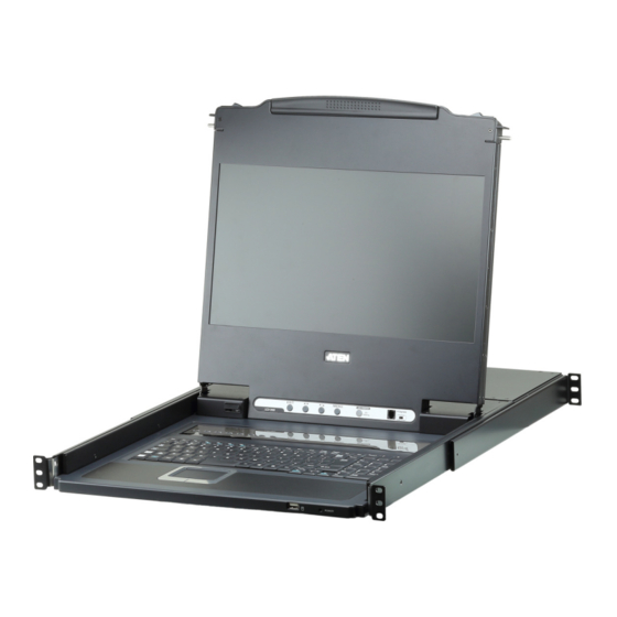
- Page 1 Single Rail 8-Port DVI FHD LCD KVM Switch CL6708MW User Manual www.aten.com...
-
Page 2: Emc Information
CL6708MW User Manual EMC Information FEDERAL COMMUNICATIONS COMMISSION INTERFERENCE STATEMENT: This equipment has been tested and found to comply with the limits for a Class A digital device, pursuant to Part 15 of the FCC Rules. These limits are designed to provide reasonable protection against harmful interference when the equipment is operated in a commercial environment. -
Page 3: User Information
CL6708MW User Manual User Information Online Registration Be sure to register your product at our online support center: International http://eservice.aten.com Telephone Support For telephone support, call this number: International 886-2-8692-6959 China 86-400-810-0-810 Japan 81-3-5615-5811 Korea 82-2-467-6789 North America 1-888-999-ATEN ext 4988... -
Page 4: Package Contents
© Copyright 2020 ATEN® International Co., Ltd. Manual Date: 2020-08-14 ATEN and the ATEN logo are registered trademarks of ATEN International Co., Ltd. All rights reserved. All other brand names and trademarks are the registered property of their respective owners. -
Page 5: Table Of Contents
CL6708MW User Manual Contents EMC Information ..........ii RoHS. - Page 6 CL6708MW User Manual LCD OSD Configuration ........23 The LCD Buttons.
- Page 7 Connection Table ......... . . 69 CL6708MW to Compatible 8-Port Switches ....69 Supported KVM Switches .
-
Page 8: About This Manual
CL6708MW User Manual About this Manual This user manual is provided to help you get the most from your CL6708MW system. It covers all aspects of installation, configuration and operation. An overview of the information found in the manual is provided below. -
Page 9: Conventions
For information about all ATEN products and how they can help you connect without limits, visit ATEN on the Web or contact an ATEN Authorized Reseller. Visit ATEN on the Web for a list of locations and telephone numbers: International http://www.aten.com... - Page 10 CL6708MW User Manual This Page Intentionally Left Blank...
-
Page 11: Chapter 1. Introduction
Introduction Overview The CL6708MW Single Rail 8-Port DVI FHD LCD KVM Switch features an integrated 17.3" LED-backlit LCD panel allowing access to and control of up to 8 computers. As many as 8 additional switches can be cascaded bringing the total number of connected computers to 64. -
Page 12: Features
Controls eight Single Link DVI computers Supports an external console with DVI video port Exclusive LED illumination light – designed by ATEN to illuminate the keyboard and touchpad to allow visibility in low-light conditions KVM Port extendable via one level cascade (CS1768) ... - Page 13 Chapter 1. Introduction Console mouse port emulation/bypass feature supports most mouse drivers Optional rack mount kits available, including easy installation options Firmware upgradable Mac/Sun keyboard support and emulation* Multilingual OSD supports English, German, Japanese, Traditional Chinese and Simplified Chinese ...
-
Page 14: Requirements
1920 x 1080 @ 60Hz. Make sure that none of the computer resolution settings exceed the LCD monitor's maximum resolution. At least one USB port. Direct support Sun USB systems; or, for Sun legacy systems, an ATEN CV130A Sun Console Converter. Cables Substandard cables may damage the connected devices or degrade overall performance. -
Page 15: Operating Systems
Chapter 1. Introduction Operating Systems Supported operating systems are shown in the table below: Version Windows 2000 or later Linux RedHat 9.0 or later SuSE 10 or later Debian 3.1 or later Ubuntu 7.04 or later UNIX 4.3 or later FreeBSD 5.5 or later Solaris 8 or later... -
Page 16: Components
CL6708MW User Manual Components Front View... - Page 17 Chapter 1. Introduction Component Description Upper Handle Pull to slide the LCD module out; push to slide it in. See Opening the Console, page 19, for details on sliding the console in and out. Module Release In order to slide the console out, you must first release it by Catches sliding these catches to the inside.
-
Page 18: Rear View
This is a standard 3 prong AC power socket. The power cord from an AC source plugs in here. Power Switch This is a standard rocker switch that powers the CL6708MW on and off. External For flexibility and convenience, the CL6708MW supports an Console Section independent, external, KVM console. -
Page 19: Chapter 2. Hardware Setup
Chapter 2 Hardware Setup Overview The CL6708MW is a switch designed to work with USB interfaces. It utilizes custom KVM cables that serve as intermediaries between the switch and computers. A custom KVM cable is required for each computer. Custom cables of various lengths are listed on page 4. -
Page 20: Standard Rack Mounting
CL6708MW User Manual Standard Rack Mounting A standard rack mounting kit is provided with your CL6708MW and can be mounted in 1U of rack space. The installation procedures are described in the following sections. Below is an image of the parts included with your package that will be needed for rack installation. - Page 21 Chapter 2. Hardware Setup To rack mount the CL6708MW, do the following: 1. Have one person position the unit in the rack and hold it steady. Have the second person screw the front brackets to the rack. 2. While the first person still holds the unit in place, the second person slides the left &...
-
Page 22: Optional Rack Mount Kits
Grounding To prevent damage to your installation it is important that all devices are properly grounded. Use a grounding wire to ground the CL6708MW by connecting one end of the wire to the grounding terminal, and the other end of... -
Page 23: Single Level Installation
(see page 15 for step 2). To set up a single level installation do the following: 1. Ground the CL6708MW by connecting one end of a grounding wire to the grounding terminal, and the other end of the wire to a suitable grounded object. - Page 24 CL6708MW User Manual Single Level Installation Diagram...
-
Page 25: Cabling Diagrams
Chapter 2. Hardware Setup Cabling Diagrams Console Cable Installation KVM Cable Installation USB KVM Cable Connection... -
Page 26: Multi-Level Installation
After the Second and First stage units have been powered on, the computers can be powered on. * The CL6708MW can only be installed as the first switch in a two-level installation as its LCD, keyboard and mouse are used as the console and all... - Page 27 Chapter 2. Hardware Setup Two Level Installation Diagram CONSOLE CL6708MW CONSOLE CS1768...
- Page 28 CL6708MW User Manual This Page Intentionally Left Blank...
-
Page 29: Chapter 3. Basic Operation
Chapter 3 Basic Operation Opening the Console The CL6708MW's console is located under the top cover. To access the console, slide the console module out and raise the cover. Note: As a safety precaution, to keep the console from accidentally sliding out, the console is locked into the In position. -
Page 30: Closing The Console
CL6708MW User Manual 2. Slide the module all the way out until it automatically locks in place. 3. Open the cover. Closing the Console To slide the console module back in, do the following: 1. Close the cover. 2. Push the module all the way in until it automatically locks in place. -
Page 31: Operating Precautions
Chapter 3. Basic Operation Operating Precautions The maximum load bearing capacity of the keyboard module is 30kg. Failure to heed the information below can result in damage to the keyboard module. Right! Rest your hands and arms lightly on the keyboard module as you work. -
Page 32: Powering Off And Restarting
CL6708MW User Manual Powering Off and Restarting If it becomes necessary to power off the CL6708MW, do the following before restarting it: 1. Shut down all the computers that are attached to the CL6708MW. Note: Unplug the power cords of any computers that have the Keyboard Power On function. -
Page 33: Lcd Osd Configuration
Chapter 3. Basic Operation LCD OSD Configuration The LCD Buttons The LCD OSD allows you to set up and configure the LCD display. Four buttons are used to perform the configuration, as described in the table, below: Button Function MENU When you have not entered the LCD OSD Menu function, pressing this button invokes the Menu function, and brings up... -
Page 34: Lcd Adjustment Settings
CL6708MW User Manual LCD Adjustment Settings An explanation of the LCD OSD adjustment settings is given in the table below: Setting Explanation Brightness Adjusts the background black level of the screen image. Contrast Adjusts the foreground white level of the screen image. -
Page 35: Hot Plugging
Chapter 3. Basic Operation Hot Plugging The CL6708MW supports hot plugging – components can be removed and added back into the installation by unplugging their cables from the ports without the need to shut the unit down. In order for hot plugging to work... -
Page 36: Port Id Numbering
CL6708MW User Manual Port ID Numbering Each port on a CL6708MW installation is assigned a unique Port ID. You can directly access any computer on any level of the installation by specifying the Port ID that the computer is connected to – either with the OSD (see OSD Operation, page 27), or with the Hotkey port selection method (see Keyboard Port Operation, page 41). -
Page 37: Chapter 4. Osd Operation
OSD Hotkey You can display the OSD on the console monitor while also viewing the display of any port on the CL6708MW by pressing the [Scroll Lock] key twice. Note: You can optionally change the OSD hotkey to the Ctrl key, in which case you would press [Ctrl] twice (see OSD HOTKEY, page 32). - Page 38 CL6708MW User Manual Note: Press once to invoke the feature, press again to exit.
-
Page 39: Osd Main Screen
Chapter 4. OSD Operation OSD Main Screen When you invoke the OSD, a screen similar to the one below appears: Note: 1. The diagram depicts the administrator's main screen. The user main screen does not show the F4 and F6 functions, since these are reserved for the administrator and can't be accessed by users. -
Page 40: Osd Navigation
CL6708MW User Manual OSD Navigation To dismiss the menu, and deactivate OSD, click the X at the upper right corner of the OSD window; or press [Esc]. To log out, click F8 at the top of the main screen, or press [F8]. -
Page 41: F1: Goto
Chapter 4. OSD Operation F1: GOTO Clicking the F1 field or pressing [F1] activates the GOTO function. GOTO allows you to switch directly to a port either by keying in the port's Name, or its Port ID. To use the name method, key in 1; key in the port's Name; then press [Enter]. -
Page 42: F3: Set
CL6708MW User Manual F3: SET This function allows the administrator and each user to set up his own working environment. A separate profile for each is stored by the OSD and is activated according to the username that was provided during login. - Page 43 Chapter 4. OSD Operation (Continued from previous page.) Setting Function SCAN–SKIP Selects which computers will be accessed under skip mode (see MODE F5: SKP, page 37), and Auto Scan mode (see F7: SCAN, page 38). Choices are: ALL - All the ports which have been set accessible (see SET ACCESSIBLE PORTS, page 34);...
-
Page 44: F4: Adm
CL6708MW User Manual F4: ADM F4 is an administrator only function. It allows the administrator to configure and control the overall operation of the OSD. To change a setting double-click it, or use the up and down arrow keys to move the highlight bar to it then press [Enter]. - Page 45 Chapter 4. OSD Operation (Continued from previous page.) Setting Function SET LOGOUT If there is no input from the console for the amount of time set with TIMEOUT this function, the user is automatically logged out. A login is necessary before the console can be used again. This enables other users to gain access to the computers when the original user is no longer accessing them, but has forgotten to log out.
- Page 46 3. Press [Esc] to exit. The operating system you selected is assigned to the KVM port. FIRMWARE In order to upgrade the CL6708MW firmware (see page 53), you UPGRADE must first enable Firmware Upgrade mode with this setting. When you bring up this menu, the current firmware version and manufacturing number are displayed.
-
Page 47: F5: Skp
Chapter 4. OSD Operation Setting Function Sets the video signal for each KVM port for the computers attached to the CL6708MW. COMPUTER VIDEO INPUT Options are: DVI-A DVI-D F5: SKP Clicking the F5 field or pressing [F5] invokes Skip (SKP) mode. This function enables you to easily skip backward or forward –... -
Page 48: F7: Scan
CL6708MW User Manual While BRC mode is in effect, the mouse will not function normally. You must exit BRC mode in order to regain control of the mouse. To exit BRC mode, invoke the OSD (with the OSD hotkey), then click the F6 field, or press [F6], to turn BRC mode off. -
Page 49: F8: Lout
Chapter 4. OSD Operation F8: LOUT Clicking the F8 field, or pressing [F8] logs you out of OSD control of the computers, and blanks the console screen. This is different from simply pressing [Esc] when you are at the main screen to deactivate the OSD. With this function you must log in all over again to regain access to the OSD, whereas with [Esc], all you have to do to reenter the OSD is tap the OSD hotkey. - Page 50 CL6708MW User Manual This Page Intentionally Left Blank...
-
Page 51: Keyboard Port Operation
Keyboard Port Operation Hotkey Port Control Hotkey port control allows you to provide KVM focus to a particular computer directly from the keyboard. The CL6708MW provides the following hotkey port control features: Selecting the Active Port Auto Scan Mode Switching ... -
Page 52: Number Lock And Minus Keys
CL6708MW User Manual Note: Press once to invoke the feature; press again to exit. Number Lock and Minus Keys 1. Hold down the Num Lock key; 2. Press and release the minus key; 3. Release the Num Lock key: [Num Lock] + [-] Control and F12 Keys 1. -
Page 53: Auto Scan Mode
Chapter 5. Keyboard Port Operation 1. Invoke hotkey mode with the [Num Lock] + [-] or [Ctrl] + [F12] combination. 2. Key in the port ID. The port ID numbers display on the command line as you key them in. If you make a mistake, use [Backspace] to erase the wrong number. - Page 54 CL6708MW User Manual To resume Auto Scanning, press any key or left-click. Scanning continues from where it left off. While Auto Scan mode is in effect, ordinary keyboard and mouse functions are suspended – only Auto Scan mode compliant keystrokes and mouse clicks can be input.
-
Page 55: Skip Mode
Chapter 5. Keyboard Port Operation Skip Mode This feature allows you to switch between computers in order to monitor them manually. You can dwell on a particular port for as long as you like – as opposed to auto-scanning, which automatically switches after a fixed interval. To invoke Skip mode, key in the following hotkey combination: 1. -
Page 56: Computer Keyboard / Mouse Reset
CL6708MW User Manual Computer Keyboard / Mouse Reset If the keyboard or mouse cease to function on the computer connected to the currently selected port, you can perform a keyboard / mouse reset on the computer. This function is essentially the same as unplugging and replugging the keyboard and mouse on the target computer. -
Page 57: Quick Hotkey Control
Chapter 5. Keyboard Port Operation Quick Hotkey Control The Quick Hotkey (see HOTKEY, page 33) can be toggled between [Num Lock] + [-], and [Ctrl] + [F12]. To toggle the Quick Hotkey: 1. Invoke hotkey mode with the [Num Lock] + [-] or [Ctrl] + [F12] combination. -
Page 58: Port Os Control
CL6708MW User Manual Port OS Control A port’s operating system can be changed to match that of the computer attached to the port. To change a port’s operating system, key in the following hotkey combination: 1. Invoke hotkey mode with the [Num Lock] + [-] or [Ctrl] + [F12] combination. -
Page 59: Restore Default Values
Chapter 5. Keyboard Port Operation Restore Default Values This administrator only hotkey restores the CL6708MW default values. See RESTORE DEFAULT VALUES, page 35. To restore the default values, key in the following hotkey combination: 1. Invoke hotkey mode with the [Num Lock] + [-] or [Ctrl] + [F12] combination. -
Page 60: Hotkey Summary Table
CL6708MW User Manual Hotkey Summary Table [Num Lock] [PN] [Enter] Switches KVM, Audio and USB focus directly to the computer that corresponds to + [-] that port ID. (PN = port number) [A] [Enter] Starts Auto Scan. The KVM focus cycles... -
Page 61: Chapter 6. Keyboard Emulation
Chapter 6 Keyboard Emulation Mac Keyboard The PC compatible (101/104 key) keyboard can emulate the functions of the Mac keyboard. The emulation mappings are listed in the table below. PC Keyboard Mac Keyboard [Shift] Shift [Ctrl] Ctrl [Ctrl] [1] [Ctrl] [2] [Ctrl] [3] [Ctrl] [4] [Alt]... -
Page 62: Sun Keyboard
CL6708MW User Manual Sun Keyboard The PC compatible (101/104 key) keyboard can emulate the functions of the Sun keyboard when the control key [Ctrl] is used in conjunction with other keys. The corresponding functions are shown in the table below. -
Page 63: The Firmware Upgrade Utility
The Firmware Upgrade Utility Introduction The purpose of the Windows-based Firmware Upgrade Utility is to provide an automated process for upgrading all CL6708MW switches in an installation. The program comes as part of a Firmware Upgrade Package that is specific for each device. -
Page 64: Preparation
CL6708MW User Manual Preparation To prepare for the firmware upgrade, do the following: 1. Use the Firmware Upgrade Cable provided with this unit to connect a COM port on your computer to the Firmware Upgrade Port of your switch. 2. Shut down all the computers on the KVM installation. -
Page 65: Starting The Upgrade
Chapter 7. The Firmware Upgrade Utility Starting the Upgrade To upgrade the firmware: 1. Run the downloaded firmware upgrade package file either by double- clicking the file icon, or by opening a command line and entering the full path to it. The Firmware Upgrade Utility welcome screen appears: Note: The screens shown in this section are for reference only. - Page 66 CL6708MW User Manual 4. Click Next to perform the upgrade. If you enabled Check Firmware Version, the Utility compares the device's firmware level with that of the upgrade files. If it finds that the device's version is higher than the upgrade version, it brings up a dialog box informing you of the situation and gives you the option to continue or cancel.
-
Page 67: Upgrade Succeeded
Chapter 7. The Firmware Upgrade Utility Upgrade Succeeded After the upgrade has completed, a screen appears to inform you that the procedure was successful. Click Finish to close the Firmware Upgrade Utility. -
Page 68: Upgrade Failed
CL6708MW User Manual Upgrade Failed If the firmware upgrade fails (Upgrade Succeeded screen does not appear), you can recover the situation. Possible reasons for firmware upgrade failure are: When a firmware upgrade was manually aborted. When the unit’s firmware becomes corrupted for some reason and you are unable to operate it. -
Page 69: Appendix
Appendix Safety Instructions General This product is for indoor use only. Read all of these instructions. Save them for future reference. Follow all warnings and instructions marked on the device. Do not place the device on any unstable surface (cart, stand, table, etc.). If the device falls, serious damage will result. - Page 70 CL6708MW User Manual If an extension cord is used with this device make sure that the total of the ampere ratings of all products used on this cord does not exceed the extension cord ampere rating. Make sure that the total of all products plugged into the wall outlet does not exceed 15 amperes.
-
Page 71: Rack Mounting
Appendix Rack Mounting Before working on the rack, make sure that the stabilizers are secured to the rack, extended to the floor, and that the full weight of the rack rests on the floor. Install front and side stabilizers on a single rack or front stabilizers for joined multiple racks before working on the rack. -
Page 72: Consignes De Sécurité
CL6708MW User Manual Consignes de sécurité Général Ce produit est destiné exclusivement à une utilisation à l’intérieur. Veuillez lire la totalité de ces instructions. Conservez-les afin de pouvoir vous y référer ultérieurement. Respectez l’ensemble des avertissements et instructions inscrits sur l’appareil. - Page 73 Appendix L’équipement doit être installé à proximité de la prise murale et le dispositif de déconnexion (prise de courant femelle) doit être facile d’accès. La prise murale doit être installée à proximité de l’équipement et doit être facile d’accès. ...
-
Page 74: Montage Sur Bâti
CL6708MW User Manual L’unité a été exposée à la pluie ou à l’eau. L’unité est tombée ou le boîtier a été endommagé. Les performances de l’unité sont visiblement altérées, ce qui indique la nécessité d’une réparation. L’unité ne fonctionne pas normalement bien que les instructions d’utilisation soient respectées. - Page 75 Appendix Assurez-vous que la température ambiante de fonctionnement de l’environnement du bâti ne dépasse pas la température ambiante maximale spécifiée pour l’équipement par le fabricant. Ne marchez sur aucun appareil lors de la maintenance d’autres appareils d’un bâti.
-
Page 76: Technical Support
Manufacturing Number The “MFG Number” (Manufacturing Number) is an internal serial number used by ATEN’s factory and technical support staff to identify products. This number does not affect products’ warranty. If your product requires after-sales services, you may provide the MFG Number to ATEN’s sales or technical support staff to identify the product and model number. -
Page 77: Specifications
Appendix Specifications Function CL6708MW Computer Direct Connections Max. Console Selection OSD, Hotkey, Pushbutton Connectors KVM Ports 8 x DVI-I Female (White) 8 x USB Type B Female 8 x 3.5mm Audio Jack Female (Green) External Console 1 x DVI-I Female (White) 2 x USB Type A Female 1 x 3.5mm Audio Jack Female (Green) - Page 78 CL6708MW User Manual Function CL6708MW Physical Housing Metal + Plastic Properties Weight 12.70 kg (27.97 lb) Dimensions 48.00 x 68.92 x 4.40 cm (L x W x H) (18.9 x 27.13 x 1.73 in.)
-
Page 79: Connection Table
49–56 57–64 Supported KVM Switches The table below lists the KVM switch that is compatible with the CL6708MW and the type of expansion that it uses. The switch listed below is sold separately. Contact your dealer for details. Expansion Type... -
Page 80: Restoring Factory Default Settings
CL6708MW User Manual Restoring Factory Default Settings You can hardware restore the factory default settings of the unit. Restoring the settings will remove all created administrator and user accounts, port names and settings. Note: A jumper cap is required when performing this procedure. -
Page 81: Osd Factory Default Settings
Appendix OSD Factory Default Settings The factory default settings are as follows: Setting Default OSD Hotkey [Scroll Lock] [Scroll Lock] Port ID Display Position Upper Left Corner Port ID Display Duration 3 Seconds Port ID Display Mode Port Number plus Port Name Scan Duration 5 Seconds Scan-Skip Mode... -
Page 82: Troubleshooting
CL6708MW User Manual Troubleshooting Operation problems can be due to a variety of causes. The first step in solving them is to make sure that all cables are securely attached and seated completely in their sockets. In addition, updating the product’s firmware may solve problems that have been discovered and resolved since the prior version was released. -
Page 83: Limited Warranty
ATEN will provide a repair service, without charge, during the Warranty Period. If a product is detective, ATEN will, at its discretion, have the option to (1) repair said product with new or repaired components, or (2) replace the entire product with an identical product or with a similar product which fulfills the same function as the defective product.
Need help?
Do you have a question about the CL6708MW and is the answer not in the manual?
Questions and answers