Sign In
Upload
Download
Table of Contents
Contents
Add to my manuals
Delete from my manuals
Share
URL of this page:
HTML Link:
Bookmark this page
Add
Manual will be automatically added to "My Manuals"
Print this page
×
Bookmark added
×
Added to my manuals
Manuals
Brands
Beckhoff Manuals
Adapter
BK11 0 Series
Documentation
Beckhoff BK11 0 Series Documentation
Ethercat bus coupler
Hide thumbs
1
2
3
4
5
6
7
8
9
10
11
12
13
14
15
16
17
18
19
20
21
22
23
24
25
26
27
28
29
30
31
32
33
34
35
36
37
38
39
40
41
42
43
44
45
46
47
48
49
50
51
52
53
54
55
56
57
58
59
60
61
62
63
64
65
66
67
68
69
70
71
72
73
74
75
76
77
78
79
80
81
82
83
84
85
86
87
88
page
of
88
Go
/
88
Contents
Table of Contents
Bookmarks
Table of Contents
Table of Contents
2 Foreword
Notes on the Documentation
Safety Instructions
Documentation Issue Status
Version Identification of Ethercat Devices
Fig. 1 EL5021 el Terminal, Standard IP20 IO Device with Batch Number and Revision ID (Since 2014/01)
Fig. 2 EK1100 Ethercat Coupler, Standard IP20 IO Device with Batch Number
Fig. 3 CU2016 Switch with Batch Number
Fig. 4 EL3202-0020 with Batch Numbers 26131006 and Unique ID-Number 204418
Fig. 5 EP1258-00001 IP67 Ethercat Box with Batch Number 22090101 and Unique Serial Number 158102
Fig. 6 EP1908-0002 IP76 Ethercat Safety Box with Batch Number 071201FF and Unique Serial Number 00346070
Fig. 7 EL2904 IP20 Safety Terminal with Batch Number/Date Code 50110302 and Unique Serial Num- Ber 00331701
Fig. 8 ELM3604-0002 Terminal with ID Number (QR Code) 100001051 and Unique Serial Number 44160201
3 Product Overview
Introduction
Fig. 9 Bus Couplers BK1120 and BK1150
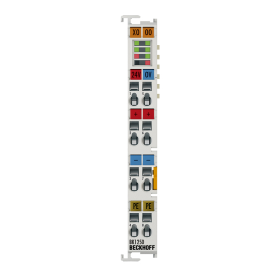
Fig. 10 BK1250
Fig. 11 K-Bus_E-Bus
Technical Data
4 Basic Principles
System Properties
Fig. 12 Ethercat Telegram Structure
Fig. 13 Ethercat Topology
The Beckhoff Bus Terminal System
Coe Interface
Fig. 14 "Coe Online " Tab
Fig. 15 Startup List in the Twincat System Manager
Fig. 16 Offline List
Ethercat State Machine
Fig. 17 Online List
Fig. 18 States of the Ethercat State Machine
Leds and Connection
Leds
Fig. 19 Diagnostic Leds at Bus Coupler BK1120
Fig. 20 Diagnostic Leds at Bus Coupler BK1150
Fig. 21 Diagnostic Leds at Bus Coupler BK1250
Connection BK1120 and BK1150
Fig. 22 BK1120, BK1150 Connection
Connection BK1250
Fig. 23 BK1250 Connection
5 Mounting and Wiring
Instructions for ESD Protection
Fig. 24 Spring Contacts of the Beckhoff I/O Components
Installation on Mounting Rails
Fig. 25 Attaching on Mounting Rail
Fig. 26 Disassembling of Terminal
Fig. 27 Power Contact on Left Side
Installation Instructions for Enhanced Mechanical Load Capacity
Installation Positions
Fig. 28 Recommended Distances for Standard Installation Position
Power Supply, Potential Groups
Fig. 29 Other Installation Positions
Ethernet Cable
Fig. 30 Potential Diagram Ekxxxx
Ethercat Wiring
ATEX - Special Conditions (Extended Temperature Range)
ATEX Documentation
6 Parameterization and Commissioning
Start-Up Behavior of the Bus Coupler
Ekxxxx - Optional Distributed Clocks Support
Fig. 31 Flow Chart Showing Start-Up Behavior of the Bus Coupler
Fig. 32 DC Tab for Indicating the Distributed Clocks Function
Fig. 33 Advanced Distributed Clocks Settings in the Ethercat Master
KL Register Communication
Parameterization of KL Terminals
Fig. 34 Twincat Setting for Using this Component as Reference Clock
Fig. 35 Register Access on KL Terminals
Configuration of KL Terminals Via Ethercat
Fig. 38 Entry
Fig. 36 Insert Dialog
Fig. 37 Data Entry
Fig. 39 Complete Terminal Access
Online Parameterization of KL Terminals Via Coe
Fig. 40 Access to Two KL Terminals
Fig. 41 Online Coe Directory of the Bk11X0
Online Parameterization of KL Terminals Via Aoe
Fig. 42 Activation of the Aoe Netid
Beckhoff Coupler Tables
Fig. 43 Table 9 with Terminal Type
Twincat System Manager
BK1120, BK1150 - Configuration Overview
Fig. 44 Twincat Tree Showing BK1120 as Example
BK1250 - Configuration Overview
Fig. 45 Twincat Tree BK1250
Inputs - Configuration Overview
Outputs - Configuration Overview
Fig. 46 Couplerstate, "Online" Tab
Status of the Working Counter (Wc State) - - Configuration Overview
Fig. 47 Couplercrtl, "Online" Tab
Online Status (Info Data) - Configuration Overview
Fig. 48 Wcstate, "Online" Tab
Fig. 49 State, "Online" Tab
ADS Address (Adsaddr) - Configuration Overview
Fig. 50 Adsaddr, "Online" Tab
Ethercat Cycle Time - Configuration Overview
Object Description
Fig. 51 BK1250, "BK1250" Tab
Mapping the Bus Terminals
Process Image Example
Fig. 52 Configuration Example for Explaining the Process Image
KS2000 Configuration Software
Example: Parameterization with the KS2000 Configuration Software
Fig. 53 Configuration Software KS2000
Fig. 54 Twincat System Manager: Ethercat Tab for Box Bk11X0/Bk1250
Fig. 55 Dialog "Ethercat", "Advanced Settings", "Aoe
Fig. 56 Twincat System Manager: "Mailbox" Dialog, Transfer of Amsservernetid
Fig. 57 KS2000: "ADS" Tab, Enter the Amsservernetid
Fig. 58 Confirmation of Successful Communication Test
7 Error Handling and Diagnosis
Error Messages to the Ethercat Master
Fig. 59 Switching the Logger Window On/Off
Fig. 60 Display of the Error Message al Status Code '0X0003' in the Logger Window
Fig. 61 Display of the Error Message al Status Code '0X001E - Invalid SM in Cfg' in the Logger Win- Dow
8 Appendix
General Operating Conditions
ATEX Documentation
UL Notice
Test Standards for Device Testing
Firmware Compatibility
Support and Service
List of Illustrations
Advertisement
Quick Links
1
Fig. 9 Bus Couplers Bk1120 and Bk1150
2
Fig. 19 Diagnostic Leds at Bus Coupler Bk1120
3
Error Handling and Diagnosis
Download this manual
Documentation
BK11x0, BK1250
EtherCAT Bus Coupler
Version:
Date:
4.1
25.04.2017
Table of
Contents
Previous
Page
Next
Page
1
2
3
4
5
Advertisement
Chapters
Table of Contents
4
List of Illustrations
87
Table of Contents
Need help?
Do you have a question about the BK11 0 Series and is the answer not in the manual?
Ask a question
Questions and answers
Related Manuals for Beckhoff BK11 0 Series
Adapter Beckhoff BK3 0 Series Documentation
Bus coupler for profibus-dp (90 pages)
Adapter Beckhoff BK3100 Documentation
Bus coupler for profibus-dp (90 pages)
Adapter Beckhoff BK3110 Documentation
Bus coupler for profibus-dp (90 pages)
Adapter Beckhoff BK3120 Documentation
Bus coupler for profibus-dp (90 pages)
Adapter Beckhoff BK3150 Documentation
Bus coupler for profibus-dp (90 pages)
Adapter Beckhoff BK1250 Documentation
Ethercat bus coupler (88 pages)
Adapter Beckhoff BK1120 Documentation
Ethercat bus coupler (88 pages)
Adapter Beckhoff BK1150 Documentation
Ethercat bus coupler (88 pages)
Adapter Beckhoff BK7150 Documentation
Bus coupler with cc-link slave interface (25 pages)
Adapter Beckhoff ControlNet BK7000 Manual
(29 pages)
Adapter Beckhoff EK9300 Documentation
Profinet-bus coupler for ethercat terminals (62 pages)
Adapter Beckhoff CU8871-0000 Installation And Operating Instructions Manual
Cfast card adapter with usb connector (19 pages)
This manual is also suitable for:
Bk1250
Bk1120
Bk1150
Table of Contents
Print
Rename the bookmark
Delete bookmark?
Delete from my manuals?
Login
Sign In
OR
Sign in with Facebook
Sign in with Google
Upload manual
Upload from disk
Upload from URL


Need help?
Do you have a question about the BK11 0 Series and is the answer not in the manual?
Questions and answers