Table of Contents
Advertisement
Quick Links
Advertisement
Table of Contents

Related Manuals for Beckhoff ControlNet BK7000


Summary of Contents for Beckhoff ControlNet BK7000
- Page 1 ControlNet Coupler BK7000 Version: 0.9.1 Last change: 2006-10-30...
-
Page 2: Table Of Contents
Liability Conditions Delivery conditions Copyright Safety Instructions State at Delivery Description of safety symbols 2. Basic information The Beckhoff bus terminal system The interfaces Power supply Power supply to the power contacts Power contacts Fieldbus connection Configuration interface K-bus contacts... -
Page 3: Foreword
In addition, the general delivery conditions of the company Beckhoff Automation GmbH apply. Copyright © This documentation is copyrighted. Any reproduction or third party use of this publication, whether in whole or in part, without the written permission of Beckhoff Automation GmbH, is forbidden. BK 7000... -
Page 4: Safety Instructions
All the components are supplied in particular hardware and software configurations appropriate for the application. Modifications to hardware or software configurations other than those described in the docu- mentation are not permitted, and nullify the liability of Beckhoff Automation GmbH. Description of safety symbols The following safety symbols are used in this documentation. -
Page 5: Basic Information
Bus couplers for all current The Beckhoff bus terminal system combines the advantages of a bus sys- bus systems tem with the functionality of compact terminals. Bus terminals can be used... - Page 6 Basic information Power input terminals Three power contacts pass the operating power to the following terminals. You can use power input terminals to subdivide the terminal row as desired separately powered groups into groups, each with a separate power supply. These power input termi- nals are not taken into account for addressing the terminals, you can insert them at any position along the terminal row.
-
Page 7: The Interfaces
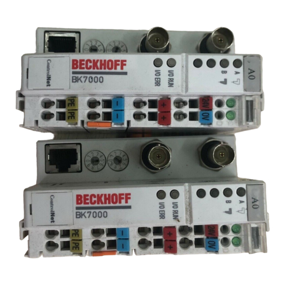
Basic information The interfaces There are six ways of making a connection to a ControlNet bus coupler. These interfaces are designed as plug connections and spring terminals. ControlNet coupler BK7000 ControlNet Power LEDs Field Bus Bus coupler / power contacts Connector A Terminal bus Field Bus... -
Page 8: Configuration Interface
Basic information Configuration interface On the lower part of the front face you will find the standard bus couplers which are fitted with an RS232 interface. The miniature plug can be at- Serial interface under the tached to a PC by means of a connection cable and the configuration soft- front flap ware KS2000. -
Page 9: The Operating Modes
Basic information The operating modes When it is first switched on the bus coupler carries out a self-test to check the functions of its components and the communications of the K bus, and while this is going on the red I/O LED will flash. When the self-test has been completed successfully, the bus coupler will begin to test the at- tached bus terminals (the "bus terminal test”) and read in the configuration from which it constructs an internal structure list, which is not accessible... -
Page 10: Mechanical Design
Basic information Mechanical design The Beckhoff bus terminal system is remarkable for its compact construc- tion and high degree of modularity. When you design the installation you will need to plan for one bus coupler and some number of bus terminals. - Page 11 Basic information The connection between bus couplers and bus terminals is automatically effected by latching the components together. The K bus is responsible for passing data and power to the electronic components of the bus terminals. In the case of digital bus terminals, the field logic receives power via the power contacts.
-
Page 12: Electrical Data
Using a special power supply terminal (KL9400), power can be fed back into the K-bus at any chosen point. If you wish to use a power supply ter- minal, please contact Beckhoff’s technical support. . BK 7000... -
Page 13: The Peripheral Data In The Process Image
Basic information The peripheral data in the process image When the bus coupler is first switched on it determines the configuration of the attached input/output terminals and automatically assigns the physical slots of the input/output channels to the addresses in the process image. The bus coupler sets up an internal list of assignments in which each of the input and output channels has a specific position in the process image. - Page 14 Basic information Analog inputs/ouputs are representative of other complex multi-byte signal bus terminals (RS232, SSI sensor interface, ...) Overview of the subdivision of the process image in the bus coupler: Output data in the bus coupler byte-oriented data Ox+1 bit-oriented data Ox+y Input data in the bus coupler...
-
Page 15: Starting Operation And Diagnostics
Basic information Starting operation and diagnostics When the bus coupler is first switched on it at once checks the attached configuration. A correct start-up procedure is indicated by the red LED "I/O ERR” going out. If this LED flashes, this indicates a fault somewhere in the terminals. - Page 16 Basic information If a fault occurs during normal operation, the error code will not be output on the LEDs until the bus coupler has been requested to diagnose the bus terminals. This diagnostic request is generated after the equipment is switched on.
-
Page 17: Run Times And Reaction Times
Basic information Run times and reaction times Transfer of the signals from the input to the controller and from the control- ler to the outputs requires a run time. This is composed of various compo- nents. Transfer from the controller to the scanner, transfer through the ControlNet and transfer from the bus coupler to the outputs. -
Page 18: Controlnet Coupler Bk7000 In The Controlnet
ControlNet coupler BK7000 in the ControlNet ControlNet coupler BK7000 in the ControlNet Introducing the system The deterministic control network is a serial communication system for communication between devices that wish to exchange time-critical appli- cation information in a deterministic and predictable manner. These devi- ces include simple I/O devices, such as sensors/actuators as well as com- plex control devices such as robots, programmable logic controllers, wel- ders, process controllers, etc. -
Page 19: The Transfer Medium: Plugs And Cables
ControlNet coupler BK7000 in the ControlNet The transfer medium: plugs and cables Physics of the transmission The physical data transfer is defined in the ControlNet standard. The BK7000 supports redundant media access with the two BNC connec- tors A and B. Additionally a monitor or configurating system can be con- nected over the NAP-Port. - Page 20 ControlNet coupler BK7000 in the ControlNet To set up this connection, the following parameters of the FwdOpen- service have to be adjusted: Net O->T connection network connection type Multicast parameters fixed/variable Fixed priority Scheduled priority size No of bytes (word-aligned) of the terminal bus output data (depending on the calculating rules for terminal bus input and output data) + 4 bytes scanner status + 2 bytes transport header...
-
Page 21: Config Data Of The Assembly Object
ControlNet coupler BK7000 in the ControlNet The status code and objectic specific status code of the FwdOpen- Response can report the following codes: Status Object specific Meaning Displayed by blinking code status code IO-ERR LED: 0x00 Not available Connection successful 0x01 0x0100 Connection already in use... -
Page 22: Calculating Rules For Terminal Bus Input And Output Data Sizes
ControlNet coupler BK7000 in the ControlNet Calculating rules for terminal bus input and output data sizes There are three options for mapping analog terminals and other complex terminals: data only (if possible), complete without word-alignment, or complete with word-alignment. The input and output data sizes depend on which mapping option is chosen. -
Page 23: Configuration With Rs Networx 1.06
ControlNet coupler BK7000 in the ControlNet Configuration with RS Networx 1.06 Make sure that beckhoff.hwx is registered with regsvr32.exe. This needs to be done only once. If you aren’t sure whether this has been done already, skip to step 2. -
Page 24: Save The Configuration
ControlNet coupler BK7000 in the ControlNet Set the input and output data size for the BK7000 according to the connec- ted terminals and the desired mapping. Set the config size to 0 for default settings or 4 for custom settings. Save the configuration Configuration with RS Networx 1.03 With RS Networx 1.03 the BK7000 in standard will not be supported. -
Page 25: Appendix
Appendix Appendix Sample arrangement of a process image in the bus coupler The following example will illustrate the assignment of input/output chan- nels to the process image. Our sample construction is to consist of the following bus terminal components: For this configuration Position Function component on the track the bus coupler will create... - Page 26 Appendix Area for bit-oriented data, Relative byte Bit position Process image in Position in the address the control unit block digital outputs 12 0 POS07 12 1 POS07 12 2 POS08 12 3 POS08 12 4 POS09 12 5 POS09 12 6 POS18 12 7...
-
Page 27: Representation Of Analog Signals In The Process Image
Appendix The base addresses I0 and O0 listed here are used as relative addresses or addresses in the bus coupler. If you have an appropriate superordinate Profibus system you can use the bus master to enter these addresses at any desired position in the process image of the control unit. You can use the configuration software of the master to assign the bytes to the ad- dresses in the process image of the control unit. - Page 28 Appendix Register set of an analog channel User area OFF SET GA IN Factory settings Software version Type 0 Length Type Secondary process image The significance of the registers and status bytes is explained in the data sheets for the corresponding bus terminals. The construction of the module is identical for bus terminals with more extensive signal processing.
-
Page 29: Support And Service
Please contact your Beckhoff branch office or representative for local support and service on Beckhoff products! The addresses of Beckhoff's branch offices and representatives round the world can be found on her internet pages: http://www.beckhoff.com You will also find further documentation for Beckhoff components there.
Need help?
Do you have a question about the ControlNet BK7000 and is the answer not in the manual?
Questions and answers