
Subscribe to Our Youtube Channel
Related Manuals for Beckhoff BK7150


Summary of Contents for Beckhoff BK7150
- Page 1 Documentation BK7150 Bus Coupler with CC-Link Slave Interface Version: 1.0.0 Date: 2017-04-18...
-
Page 3: Table Of Contents
1 Foreword .............................. 5 Notes on the documentation...................... 5 Safety instructions .......................... 6 Documentation issue status...................... 7 2 Product overview............................ 8 The Beckhoff Bus Terminal system .................... 8 BK7150 - Introduction ........................ 10 Technical Data.......................... 11 3 Mounting and wiring .......................... 12 Assembly ............................ 12 3.1.1... - Page 4 Table of contents Version: 1.0.0 BK7150...
-
Page 5: Foreword
The TwinCAT Technology is covered, including but not limited to the following patent applications and patents: EP0851348, US6167425 with corresponding applications or registrations in various other countries. ® EtherCAT is registered trademark and patented technology, licensed by Beckhoff Automation GmbH, Germany Copyright © Beckhoff Automation GmbH & Co. KG, Germany. -
Page 6: Safety Instructions
All the components are supplied in particular hardware and software configurations appropriate for the application. Modifications to hardware or software configurations other than those described in the documentation are not permitted, and nullify the liability of Beckhoff Automation GmbH & Co. KG. Personnel qualification This description is only intended for trained specialists in control, automation and drive engineering who are familiar with the applicable national standards. -
Page 7: Documentation Issue Status
Foreword Documentation issue status Version Modifications 1.0.0 • Migration BK7150 Version: 1.0.0... -
Page 8: Product Overview
Bus Couplers for all usual bus systems The Beckhoff Bus Terminal system unites the advantages of a bus system with the possibilities of the compact series terminal. Bus Terminals can be driven within all the usual bus systems, thus reducing the controller parts count. - Page 9 When converting to a different bus system it is necessary to bear in mind the need to change the timeout periods if the bus cycle time is longer. The interfaces A Bus Coupler has six different methods of connection. These interfaces are designed as plug connectors and as spring-loaded terminals. BK7150 Version: 1.0.0...
-
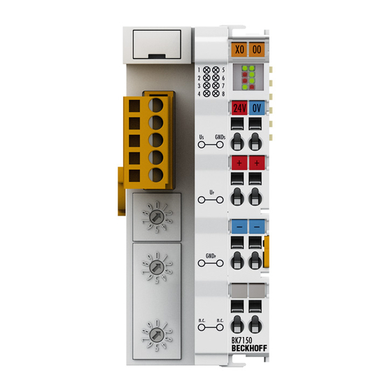
Page 10: Bk7150 - Introduction
Complex signal processing for analog I /Os, position measurement, … The BK7150 Bus Coupler supports the operation of all Bus Terminals. As far as the user is concerned, handling of the analog inputs/outputs is no different to other series. The information is available in the process image of the controller for processing in the form of a byte-array. -
Page 11: Technical Data
Bus Terminal. The controller carries out the desired setting automatically after switching on. Technical Data System data CC-Link | BK7150 Number of I/O modules Number of I/O points Depending on controller Data transfer medium... -
Page 12: Mounting And Wiring
3.1.1 Dimensions The system of the Beckhoff Bus Terminals is characterized by low physical volume and high modularity. When planning a project it must be assumed that at least one Bus Coupler and a number of Bus Terminals will be used. The mechanical dimensions of the Bus Couplers are independent of the fieldbus system. -
Page 13: Installation
Mounting and wiring Connection technology BK7150 Wiring Cage Clamp® spring-loaded system Connection cross-section 0.08 mm² ... 2.5 mm², stranded, solid wire, 28 … 14 AWG Fieldbus connection CC-Link open style connector Power contacts 3 spring contacts Current loading IMAXX 10 A (125 A short circuit) Rated voltage 24 V... -
Page 14: Installation On Mounting Rails
PE power contact The power contact labelled PE can be used as a protective earth. For safety reasons this contact mates first when plugging together, and can ground short-circuit currents of up to 125 A. Version: 1.0.0 BK7150... -
Page 15: Wiring
3.2.1 Potential groups, insulation testing and PE Potential groups A Beckhoff Bus Terminal block usually has three different potential groups: • The fieldbus interface is electrically isolated (except for individual Low Cost couplers) and forms the first potential group. • Bus Coupler / Bus Terminal Controller logic, K-bus and terminal logic form a second electrically isolated potential group. -
Page 16: Fig. 5 Potential Groups Of A Bus Terminal Block
Bus Coupler / Bus Terminal Controller can also be used for supplying the power contacts. PE power contacts The power contact labelled PE can be used as a protective earth. For safety reasons this contact mates first when plugging together, and can ground short-circuit currents of up to 125 A. Version: 1.0.0 BK7150... -
Page 17: Cc-Link
10 mm out from the connected group of other terminals. In that case, the PE conductors do not have to be disconnected. The power contact with the label PE must not be used for other potentials. 3.2.2 CC-Link Fig. 7: CC-Link-Anschluss CC-Link wiring Use a resistor (R = 110 Ω) to terminate open ends. BK7150 Version: 1.0.0... -
Page 18: Power Supply
• from an isolated source protected by a fuse of max. 4A (according to UL248) or DANGER • from a voltage supply complying with NEC class 2. An NEC class 2 voltage source must not be connected in series or parallel with another NEC class 2 voltage source! Version: 1.0.0 BK7150... -
Page 19: Fig. 10 Potential Connection Diagram Of An Ekxxxx
The current load from the power contact must not exceed 10 A for long periods. The current carrying capacity between two spring-loaded terminals is identical to that of the connecting wires. BK7150 Version: 1.0.0... - Page 20 Bus Terminal the blade contacts on the left hand side of the Bus Terminal are connected to the spring contacts. The tongue & groove design of the top and bottom of the Bus Coupler / Bus Terminal Controller and Bus Terminals enables secure fitting of the power contacts. Version: 1.0.0 BK7150...
-
Page 21: First Steps
80 DI/80 DO and/or 12 channel in/out (24 Byte in/out) 112 DI/112 DO and/or 16 channel in/out (32 Byte in/out) On start up, the BK7150 reads the terminals and configures the CC-link interface. The I/O error LED the coupler shows which mapping is active. - Page 22 1 x KL9010 32 DI / 32 DO / 4 AI / 4 AO Mapping 2 Configure with GX IEC Developer Example 1: BK7150 Node 1 2 x KL1xx4 X100...X10F 2 x KL2xx4 Y100...Y10F 1 x KL9010 8 DI / 8 DO...
- Page 23 First Steps Example 4: BK7150 Node 1 4 x KL1xx8 X100...X13F 4 x KL2xx8 Y100...Y13F 2 x KL3xx2 D100…D103 2 x KL4xx2 D200…D203 1 x KL9010 32 DI / 32 DO / 4 AI / 4 AO Mapping 2 Remote-Input (RX) X100...
-
Page 24: Appendix
Beckhoff's branch offices and representatives Please contact your Beckhoff branch office or representative for local support and service on Beckhoff products! The addresses of Beckhoff's branch offices and representatives round the world can be found on her internet pages: http://www.beckhoff.com You will also find further documentation for Beckhoff components there. - Page 25 Table of figures Table of figures Fig. 1 BK7150 ............................Fig. 2 BK7150 - Dimensions ........................Fig. 3 Release the locking mechanism by pulling the orange tab............Fig. 4 Power contact on the left ......................Fig. 5 Potential groups of a Bus Terminal block ..................
Need help?
Do you have a question about the BK7150 and is the answer not in the manual?
Questions and answers